Fan system testing, adjusting and balancing (TAB) should leave a record that another technician can follow. An airflow figure on its own is not enough. You need to know where it was measured, which operating mode was active, what had been adjusted and which project requirement the result was compared with.
The practical sequence is to establish readiness, capture a baseline, make controlled adjustments and repeat the relevant measurements. Keep the acceptance criteria beside the readings throughout. That makes the final report useful for a commissioning review, rather than a collection of numbers with missing context.
1. Define what the TAB result must demonstrate
Start with the approved design information and the operating mode to be tested. Identify the required system and terminal airflows, the applicable acceptance criteria and any unresolved design questions. A generic tolerance copied from another job cannot settle whether this installation meets its own requirements.
TAB and commissioning are related, but they are not interchangeable. Balancing records describe measured conditions and adjustments. Commissioning also needs the functional checks assigned to the project, which may include control modes, alarms and interlocks. Agree on the boundary before work starts so a completed balancing sheet is not mistaken for approval of every system function.
2. Check system readiness before recording a baseline
A baseline should describe a defined, reasonably stable system. Confirm that installation is complete for the planned test, components are clean, filters are in the intended condition, and dampers and terminals are in their required starting positions. Record the control mode and confirm that the relevant design information is available.
Safe access is part of readiness, not an item to work around. Observe rotation only while guards and safe boundaries remain in place. This checklist does not authorize exposed-moving-part checks or energized adjustments. If access, installation or control stability is unresolved, identify the exception instead of presenting a provisional reading as a final result.
3. Make airflow and pressure readings traceable
Choose the airflow and pressure method for the actual system and measurement plane. Record the station location and geometry, the instrument identity, its current calibration status and whether its range and resolution suit the measurement. Document units, averaging, density corrections where applicable, and relevant uncertainty.
A single velocity reading at an outlet or at the fan discharge does not establish total system airflow. The method and measurement plane matter. Likewise, a pressure value is difficult to interpret if the report does not identify where and under what conditions it was taken.
For background when discussing the selected fan’s operating point, see the guide to reading centrifugal fan curves. Use the exact model’s current documents for the project; a general curve explanation does not validate a field measurement.
4. Keep a baseline, change log and final record
Capture fan speed, airflow, pressure, electrical data, damper positions, filter condition, control status, sound and relevant environmental conditions before adjusting the system. Keep the original baseline. Replacing it with the final figures removes the evidence of what changed.
| Record | What it needs to preserve |
|---|---|
| Baseline | System and station identity, operating mode, instrument details, readings and starting component conditions. |
| Adjustment log | The branch, terminal or fan setting changed, its previous and new position, and the associated repeat readings. |
| Final check | Results against the agreed criteria, the tested mode and any remaining exceptions. |
| Handover | Methods, corrections, limitations and the functional checks completed or still outstanding. |
The aim is not to make every repeated reading identical. It is to leave enough context to understand differences and judge the result against the project’s requirements.
5. Adjust deliberately, then remeasure the affected system
Changing a branch, terminal or fan operating point can affect the rest of the system. Treat balancing as an iterative process: record the change, allow the intended operating condition to become stable and repeat the relevant checks. Do not assume that improving one terminal leaves every other terminal unchanged.
Keep manufacturer limits and safety functions active. The objective is the required operating condition within those boundaries, not the highest available speed or the largest possible airflow reading. Where a condition cannot be resolved within the authorized adjustment scope, record it for the appropriate engineering review.
6. Separate laboratory context from installed-system evidence
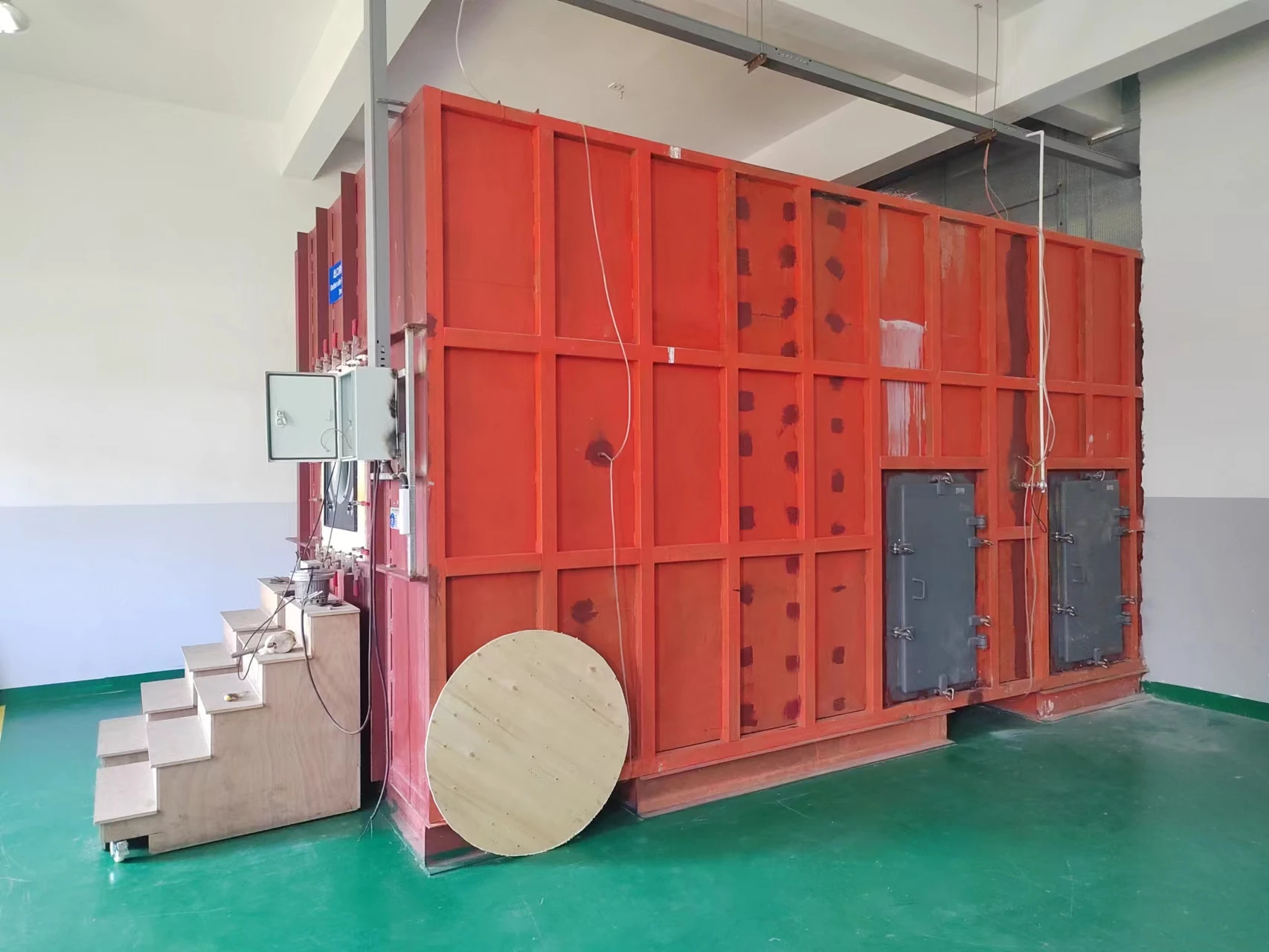
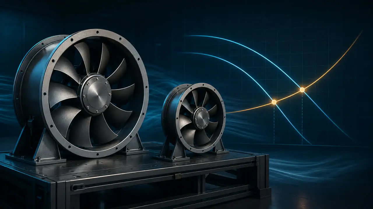
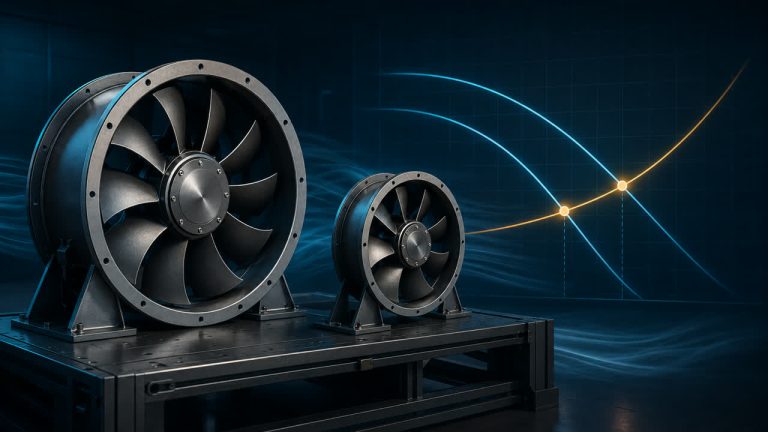
Company laboratory equipment photograph, shown as testing context only. It is not an installed-system TAB result or evidence of calibration, certification or acceptance for a particular project.
A laboratory image and an installed-system report answer different questions. For the installation, retain its own measurement stations, operating conditions and adjustment history. A photograph of test equipment cannot replace those records.
When the discussion concerns an air handling unit, the Longwell AHU plug fan range provides a starting point for identifying the equipment family. Selection still requires the actual duty, exact model information and project constraints; the category link is not a suitability recommendation.
7. Close the report with functional checks and open exceptions
Carry out the authorized final checks for the specified design modes, alarms, interlocks, reset and staging behavior. Keep their results distinct from airflow-balancing results so the reader can see exactly what was tested.
Finish with the instrument list, methods, baseline and final readings, adjustments, acceptance criteria and unresolved exceptions. A useful handover makes the remaining questions visible. It does not hide them behind a screenshot or a blanket statement that the system has passed.
For a fan selection discussion, have the required airflow, pressure, operating modes and current measurements ready.