Specifying a 48V DC cooling fan for Telecom Racks
The customer required a reliable thermal management setup for a newly developed series of telecom equipment racks. Specifically, they submitted a requirement for an initial production run of 2,400 units of a high-capacity 48V DC cooling fan. The physical footprint was strictly constrained to a standard 172mm by 51mm aluminum frame envelope. Furthermore, the entire rack system ran on a centralized 48V power rail to minimize current draw across the backplane.
Initially, their mechanical specification matched standard off-the-shelf offerings for that dimensional size. However, the telecom application demanded active, precise thermal regulation to minimize acoustic output during low-load periods. Therefore, they needed the fan equipped with a specific Pulse Width Modulation (PWM) control wire and a Frequency Generator (FG) tachometer signal. The hard aerodynamic constraints were significant.
The unit had to deliver a minimum of 305.29 CFM of airflow at an operating speed of 4,000 RPM. Meanwhile, the static pressure requirement stood at 31.7 mm H2O to push air through dense server heat sinks. Ambient temperature conditions dictated an operating range from -10°C to +60°C, typical for outdoor-adjacent telecom environments. Finally, the design needed to comply with UL Class A insulation standards and feature a 50,000-hour bearing life at 25°C. Performance figures were tested to AMCA 210-16 methods.
The Engineering Decision: Integrating PWM and Tachometer Signals
We evaluated two distinct methods for controlling this 48V DC cooling fan inside the equipment enclosure. First, we considered simple voltage regulation on a standard two-wire motor. We rejected this method because dropping the supply voltage below 26.0 VDC severely reduces the internal motor torque. Consequently, the fan could stall completely at low speeds, leading to localized overheating in the rack.
Instead, we chose to modify our existing LWAD17251 motor design to accept a four-wire configuration. By engineering a dedicated PWM circuit and integrating an FG tachometer output, the primary power rail remains constantly at 48.0 VDC. Thus, the motor retains its full electromagnetic torque even when the PWM duty cycle drops to 15 percent.
Balancing Control Precision Against Manufacturing Complexity
This engineering decision involved specific physical trade-offs. Upgrading the internal printed circuit board to handle a 20kHz PWM frequency added a materially higher cost to the final assembly. Furthermore, routing four 22AWG UL1007 lead wires instead of the standard two slightly complicated the stator winding and potting process. Even so, the resulting control precision justified the trade for this application.
We configured the internal PWM logic to start the rotor from a dead stop using a 15 percent duty cycle. At a 0 percent duty cycle, the firmware forces the fan to idle at 900 RPM rather than stopping completely. When the system sends a 50 percent signal, the speed climbs to 2,000 RPM. Finally, at a 100 percent signal, the unit hits its maximum rated 4,000 RPM.
As a critical failsafe, if the control signal wire disconnects entirely, the fan defaults to its baseline temperature control speed. The final model, designated LWAD17251HH-23-40, meets all airflow targets while maintaining an acceptable average acoustic profile of 65.0 dBA.
Technical Specifications
| Airflow | 305.29 CFM |
| Static Pressure | 31.7 mm H2O |
| Input Power | 30.72 W |
| Speed | 4000 RPM |
| Voltage | 48.0 VDC |
| Input Current | 0.64 A |
| Dimensions | 172 x 51 mm |
| Weight | 740 grams |
| Insulation Class | UL Class A |
These exact parameters define the final 48V DC cooling fan delivered to the customer. The static pressure rating of 31.7 mm H2O is the critical metric here, as axial designs typically struggle to push high volumes of air against the back pressure generated by server hardware.
Reference: AMCA 210 covers the test method behind these figures.
Technical Documentation
Download the full dimensional drawing and electrical specification sheet.
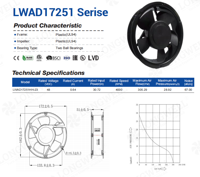
The performance graph plots static pressure against airflow, allowing system integrators to locate their exact operating point.
How to Specify Fans for Telecom Racks
If you are specifying a 48V DC cooling fan for telecom or data center racks, precise speed control prevents overcooling and reduces acoustic noise. Consider these factors before finalizing your fan specification:
- First, define the minimum duty cycle behavior. Always specify whether the fan should stop completely or maintain a baseline idle speed, like 900 RPM, when the PWM signal drops to 0 percent.
- Second, account for failsafe operation. If the PWM wire breaks or the controller fails, the fan must default to a safe baseline speed to prevent catastrophic system failure.
- Next, verify your control frequency. Standard industrial controllers often output a 20kHz or 25kHz PWM signal, so the fan’s internal circuitry must be tuned to match this exact frequency.
- Finally, because we manufacture our own stators and PCBA controllers in Ningbo, we can rapidly prototype these specific 4-wire modifications in under 90 days.
Related: DC Motors.
Engineering FAQs
Technical Documentation & Resources
Browse our axial fans range, the AC axial fans section, or EC axial fans.
Have a Similar Fan Requirement?
Longwell’s engineering team delivers custom spec sheets and samples within 90 days. Since 1990, we have supplied EC fans and blowers to OEMs across HVAC, cold chain, data center, and industrial applications worldwide.
Browse Related Products:
🏆 ISO 9001 / ISO 14001 / ISO 45001 | CE (TÜV) | UL/ETL | ATEX Zone 21/22 | AMCA 210-16 / ISO 5801 tested