The requirement
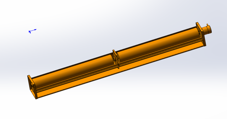
24 VDC brushless motors paired with 615mm cross-flow impellers formed the baseline requirement for this variable-frequency air conditioning project. OEM engineers initially requested three prototype sets to validate a new inverter AC unit design. The system runs on a 240V AC mains supply, but the internal control architecture rectifies this to supply a dedicated 24V rail to the fan assembly. Based on the initial sales input, the original motor specified was the LWDM92M-011. However, during 3D CAD integration, the OEM discovered a major geometric conflict.
The customer’s airflow diagram dictated a highly specific path. Intake air had to pull down across a top-mounted heat exchanger with a 130mm vertical clearance envelope, then discharge laterally through a tight 30mm exit port at the bottom left. This internal layout forced the motor to be mounted on the left side of the chassis, rather than the right. Because of this specific mounting position, the initial rotation direction was completely backward.
Both the plastic impeller (part number LWPI-φ90.5X615-08) and the new motor had to spin exactly clockwise (CW) to maintain the correct intake-to-exhaust vector. The client mandated an immediate drawing update from the technical PM. They specified the motor must operate at a rated load speed of 1500 RPM under PWM control. For the mechanical coupling, the OEM required a strict steel shaft length of 25mm with an 8.0mm diameter (-0.01/0 tolerance), explicitly stating that no flat cross-cut should be machined into the shaft end.
The engineering answer: choosing the 24v dc cross flow
Fixing the directional mismatch required more than just reversing the electrical polarity on the existing unit. Running a standard DC motor backward negatively impacts bearing life, internal magnetic efficiency, and acoustic profiles. The engineering team assigned to the project immediately spun up a revised motor design, designated LWDM92M-013, engineered specifically for clockwise (CW) rotation under the required 1500 RPM rated load condition. This 92mm diameter motor accepts the 24V DC supply (pinout: Red +24V, Blue GND, Yellow PWM, White FG) and integrates Longwell’s SmartEC™ logic for direct PWM speed regulation from the client’s mainboard.
For the air-moving component, engineers retained the 615±2mm length and 90.5mm outer diameter of the cross-flow impeller but updated the hub and shaft interface. An AS+GF30% (Acrylonitrile Styrene reinforced with 30% Glass Fiber) composite was chosen for the impeller body material. Standard ABS plastics would easily warp over a long 615mm span under continuous thermal cycling and condensation typical in an air conditioner evaporator. The glass fiber reinforcement maintains absolute mechanical rigidity. Radial runout is kept below 0.7mm, and axial runout is less than 0.6mm.
Standard manufacturing processes often apply a D-cut to motor shafts for easier set-screw mounting. The OEM explicitly rejected this geometry. Engineers modified the tooling to output a perfectly round 8mm (-0.01/0) steel shaft extending exactly 25±0.5mm. Blades were joined using ultrasonic welding (noted in the technical request as ‘welded by noise wave’) to prevent false or loose joints that could generate harmonic rattling. The final assembly undergoes dynamic balancing, leaving less than 0.3g of residual unbalance at 1200 RPM, ensuring extremely quiet operation inside the client’s domestic air conditioning unit.
Final specification
| Parameter | Specification |
|---|---|
| Motor Model | LWDM92M-013 |
| Impeller Model | LWPI-φ90.5X615-08 |
| Operating Voltage | 24 VDC |
| Rated Speed | 1500 RPM |
| Speed Control Method | PWM (Yellow Wire) |
| Rotation Direction | Clockwise (CW) |
| Impeller Dimensions | Length: 615±2 mm, Diameter: 90.5 mm |
| Motor Dimensions | Diameter: 92 mm, Length: 65±0.5 mm |
| Steel Shaft Dimensions | Length: 25±0.5 mm, Diameter: 8 mm (-0.01/0) |
| Impeller Material | AS+GF30% |
| Balancing Tolerance | ≤ 0.3g at 1200 RPM |
| Runout Tolerances | Radial < 0.7mm, Axial < 0.6mm, Shaft < 0.2mm |
These parameters demonstrate a highly constrained mechanical fit tailored to the OEM’s exact chassis design. The precise 25mm shaft length and extremely tight <0.7mm radial runout dictate precision alignment during final factory assembly, preventing any harmonic vibration across the 615mm span at the 1500 RPM operating speed.
Every figure above comes from our own test chamber, measured using AMCA 210/211 and ISO 5801 methods. The published procedures behind those numbers are available from AMCA. As always, confirm the duty point against the finished unit before release, since installation conditions move it.
Technical documents
The following approved production files and technical exchanges document the final configuration for this inverter AC project.

The sales input screenshot captures the original request for three prototype 24V EC brushless motors designed to run off a 240V AC system board.
Download Original Impeller Drawing (CCW)
The initial cross-flow impeller drawing showing the rejected counter-clockwise rotation vector.
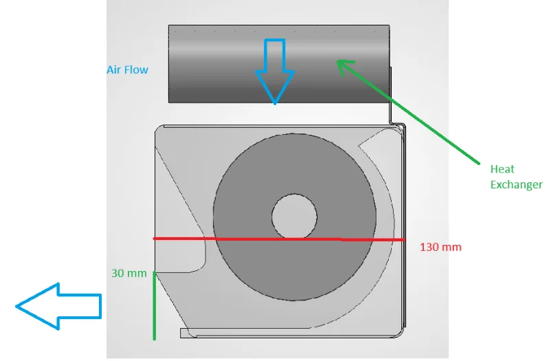
Here the system airflow diagram highlights the 130mm vertical heat exchanger clearance and the restrictive 30mm exit port.
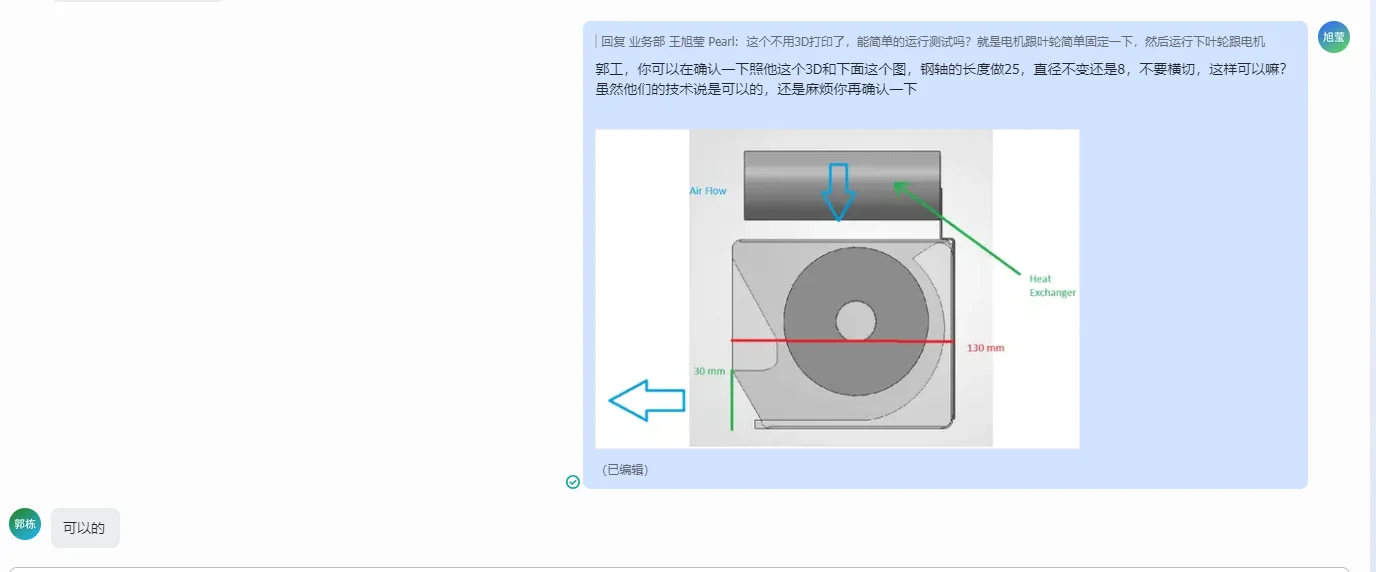
The technical PM chat confirms the required 25mm full-round shaft modification and the mandatory left-side chassis mounting.
Download Final Impeller Drawing (CW)
The final approved LWPI-φ90.5X615-08 specification sheet documenting the AS+GF30% material and CW rotation.
Download Initial Motor Specs
The initial LWDM92M-011 motor drawing, which lacked the necessary CW optimization.
Download Final Motor Specs
The final approved LWDM92M-013 technical document detailing the 24 VDC rating, CW rotation, and four-wire control pinout.
Why it landed here
- Longwell’s 90-day custom NPI speed allowed the technical PM to instantly generate updated CW-rotation motor (LWDM92M-013) drawings based on a simple 3D STEP file and engineering chat feedback.
- Direct modification of mechanical parameters—such as the exact 25mm shaft length and full-round 8mm diameter—was executed without demanding massive MOQ thresholds for the initial 3-piece prototype run.
- By manufacturing both the 24 VDC EC motor and the AS+GF30% impeller in-house, Longwell supplies the complete assembly as one part number, with no third-party component markups inside it.
- Rapid local testing verified the 1500 RPM PWM response and clockwise rotational matching before physical sampling, preventing further delays in the OEM’s inverter AC development cycle.
Explore our full cross flow fans range.
Questions that followed
Q: Why specify a 24V DC EC motor in a 240V AC inverter system?
A: Variable-frequency air conditioners convert the 240V AC mains to internal DC rails to improve overall electrical efficiency. Using a 24V DC EC motor like the LWDM92M-013 allows the mainboard to exert precise PWM speed control up to 1500 RPM, eliminating the need for a separate, bulky AC inverter dedicated solely to the fan module.
Q: What are the balancing tolerances for a 615mm cross-flow impeller?
A: Longwell engineers balance the AS+GF30% plastic impellers to leave residual unbalance at ≤ 0.3g under 1200 RPM test conditions. Radial runout is strictly kept below 0.7mm and shaft runout under 0.2mm to prevent any harmonic vibration inside the chassis.
Q: Does the motor mounting side affect cross-flow fan design?
A: Yes. Placing the motor on the left side of the chassis, as dictated by the 130mm heat exchanger clearance in this specific project, completely changes the required rotational vector. Both the 92mm motor and the plastic impeller must be physically mapped for clockwise (CW) rotation to push air through the 30mm exhaust gap correctly.
Documents for this build
Need the same thing for your own unit?
Give us the numbers and the envelope, and you get a shortlist rather than a catalog. Meanwhile custom spec sheets and samples run to 90 days. Since 1990 Longwell has supplied EC fans and blowers to OEMs in HVAC, cold chain, data center and industrial markets.
Browse Related Products:
🏆 ISO 9001 / ISO 14001 / ISO 45001 | CE (TÜV) | UL/ETL | ATEX Zone 21/22 | AMCA 210/211 / ISO 5801 tested