Adapting a Motor Housing for Specific Mechanical Fitment
The customer sent us a strict request for a new ventilation project. Meanwhile, they needed a powerful 24V DC centrifugal blower. The system required very high static pressure. First, the 24V DC centrifugal blower had to clear 800 Pa at no load.
This baseline ensured the 24V DC centrifugal blower would hold a steady 488 to 700 Pa against heavy system resistance. Next, the 24V DC centrifugal blower needed a 0-10V or PWM signal to manage fan speed. The total airflow requirement peaked at 532 m3/h. Therefore, furthermore, the physical space presented a rigid mechanical limit.
The center hole distance on the 24V DC centrifugal blower housing had to measure exactly 158 mm. In practice, this exact span allowed the 24V DC centrifugal blower to drop into their existing metal chassis. Additionally, the 24V DC centrifugal blower wiring created a weak spot. The power and signal wires exited through the motor cover.
The original setup left a small open gap. Because the equipment operates outdoors, temperatures swing wildly from -20°C to 65°C. Therefore, the customer required a fully closed wire exit. A low limit of -20°C means the machine faces harsh freezing conditions.
In short, the motor needed solid protection against wet weather. Finally, the total assembly had to pass UL 507 and EN 60335-1 safety tests. Consequently, fixing the mechanical gaps became our primary focus.
Revising the Metal Dies and Weather Seals
We looked at a few ways to solve the 158 mm center hole problem. First, we thought about using an extra metal plate. We rejected this idea. An extra plate adds useless weight.
It also creates new spots for vibration. Instead, we changed the actual metal stamping die. This change required a new design for the motor mounting plates. Consequently, this custom choice carried a materially higher initial cost.
It also added several days to the sample lead time. Even so, it gave the customer a perfect fit. They did not need to use clunky extra brackets.
Sealing the Motor Wire Gap
Next, we addressed the open gap around the motor wires. The power line (red), ground (blue), signal input (yellow), and tachometer output (white) all exit through one spot. We considered using liquid silicone glue on the factory line. We rejected the glue option immediately.
Liquid seals break down over time. The constant thermal cycling from -20°C to 65°C ruins the bond. Instead, we built a dedicated mechanical seal right into the motor cover. This solid plastic piece grips the wire harness tightly. Therefore, the fan maintains a true IP44 protection rating for years.
Achieving High Static Pressure
Finally, we selected a strong 108W motor to drive the impeller. This power rating pushes the 24V DC centrifugal blower to an absolute maximum static pressure of 969 Pa. Furthermore, it moves up to 532 m3/h of air. Therefore, the fan easily exceeds the strict 800 Pa minimum baseline.
However, this high performance brings a direct cost. The unit generates 65 dB(A) of noise at its 1750 RPM top speed. By contrast, running a slower fan reduces noise but fails to push air through thick system filters. We confirm all these numbers in a test chamber. Specifically, we test performance TO ISO 5801-1997 methods.
Technical Specifications
| Model | LWFD3G160-092SM-04-00 |
| Nominal Voltage | 24 VDC (Range: 18~36 VDC) |
| Speed | 1750 ± 10% RPM |
| Current | 4.4 ± 10% A |
| Power Input | 108 ± 10% W |
| Air Flow (Max) | 532 m3/h (313 CFM) |
| Static Pressure (Max) | 969 Pa |
| Noise Level | 65 dB(A) |
| Ambient Temperature | -20°C to 65°C |
| Insulation Class | Class B |
| Protection Type | IP44 |
| Work System | S1 |
| Certifications | CE, ETL (UL 507), RoHS, Reach |
The power input and maximum static pressure rows matter the most here. A high 108W power draw allows the motor to spin fast enough to generate 969 Pa. Consequently, the high pressure safely overcomes heavy system airflow limits.
Reference: AMCA 210 covers the test method behind these figures.
Technical Documentation
View the engineering drawing. Mechanical engineers need this to verify the 158 mm center hole modification fits their chassis.
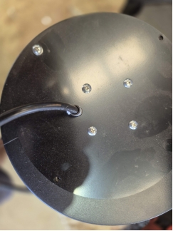 This image shows the original wire gap that required sealing, which helps quality teams understand the weak point.
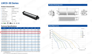
View the specification sheet. Electrical engineers need this to review the 108W input parameters and UL 507 safety ratings.
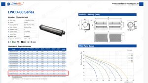
View the performance document. System designers need this P-Q curve to confirm airflow rates against their specific static pressure.
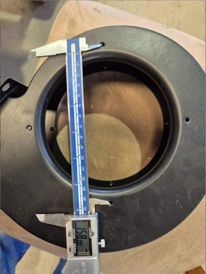 This inspection photo proves the final 158 mm hole span measurement for incoming quality control teams.
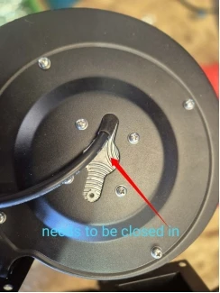 This factory photo displays the final IP44 mechanical seal, which helps inspectors verify the weatherproofing upgrade.
Specifying a Custom 24V DC centrifugal blower
Follow these direct steps when you need to drop a new fan into an old machine.
- First, measure your exact mounting holes with a caliper. Standard fans rarely fit custom chassis plates. Changing a hole distance often requires new metal dies. Therefore, note this limit early to avoid wasting time on standard units.
- Next, map out your true system resistance. A fan rating of 969 Pa represents its absolute peak limit in an empty test chamber. You must calculate the drop to ensure you get your needed 500 Pa when installed.
- Then, define your weather sealing rules. If a wire exit needs an IP44 rating in freezing conditions, tell the factory immediately. Consequently, the design engineers will avoid using cheap liquid glue that cracks under thermal stress.
- Finally, state your exact control signals. A 0-10V or PWM signal requires a matching circuit board. Specifying this clearly allows the supplier to match the correct internal motor controller.
Related: Blowers.
Engineering Questions on Custom Centrifugal Fans
Technical Documentation & Resources
Browse our blowers range, the exhaust blowers section, or centrifugal blowers.
Have a Similar Fan Requirement?
Longwell’s engineering team delivers custom spec sheets and samples within 90 days. Since 1990, we have supplied EC fans and blowers to OEMs across HVAC, cold chain, data center, and industrial applications worldwide.
Browse Related Products:
🏆 ISO 9001 / ISO 14001 / ISO 45001 | CE (TÜV) | UL/ETL | ATEX Zone 21/22 | AMCA 210-16 / ISO 5801 tested
Choose the right blower
Longwell manufactures 247 blowers in-house. Send airflow, static pressure and voltage — an engineer replies with a matching model, performance curve and price within one working day.