Ask whether fans in AI data centers are “different,” and the first temptation is to look for a special product label. That is usually the wrong starting point. There is no single fan type that becomes suitable simply because a facility supports AI computing. What changes is the duty around the fan: where heat enters the cooling chain, which portion is carried by air or liquid, how resistance changes, how controls respond, and what must happen after a component failure.
A useful selection process therefore begins with the cooling architecture, not a catalog shortlist. Axial, centrifugal, plug-fan and electronically controlled arrangements may all appear in an AI data center. Their suitability has to be demonstrated at the required operating points and within the project’s installation, control and risk boundaries.
The architecture changes the fan duty
An AI data center does not automatically require a certified category of “AI fan.” It requires fans that match a defined part of the cooling system. Start by naming that boundary: server, rack, row, room air handler, ventilation system or outdoor heat-rejection equipment. Each sees a different resistance path, control signal, maintenance constraint and consequence of interruption. Until the boundary is explicit, “How much airflow do we need?” is not a complete engineering question.
Trace the complete heat path first
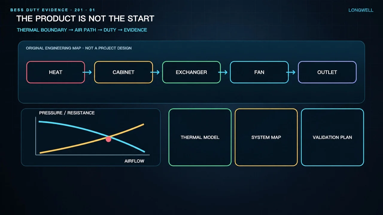
Sketch the route from the heat source to the final sink. An air-dominant path may pass through server airflow, rack inlets and outlets, containment, coils, filters, dampers and ductwork. In a liquid-assisted design, some heat moves through a liquid interface and coolant loop, while other loads may remain on air. Liquid cooling can therefore move or reduce fan responsibility without automatically eliminating it.
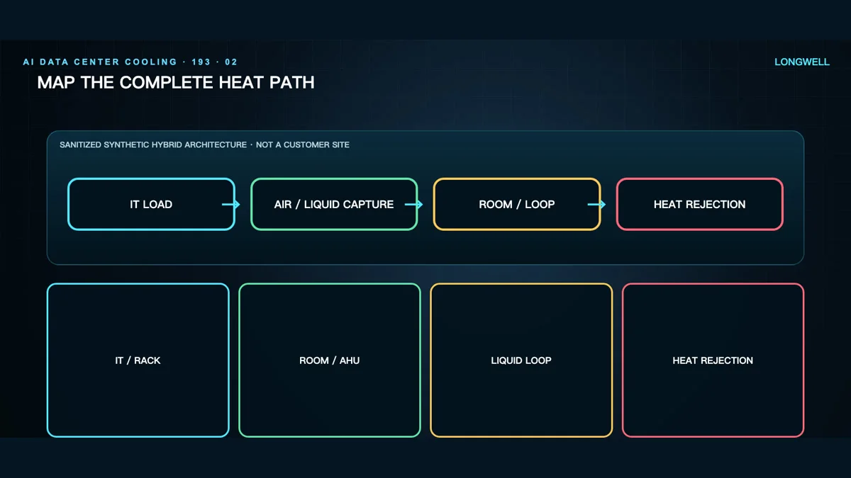
This original explanatory frame maps a conceptual heat path. It is not a customer layout, measured result or model-specific design.
For every segment, document the load it is expected to carry, its airflow or liquid-flow boundary, expected resistance, controlling sensor and response to a failed component. This exposes duplicated loads and residual heat that has no accountable cooling path.
Total airflow is not the same as useful airflow
A room can show an acceptable average temperature while one rack inlet experiences a poor condition. A total airflow figure also says little about distribution. Bypass can send supply air around the intended load, recirculation can return warm air to an inlet, and local restrictions can alter neighboring rows.
Connect facility duty to local acceptance points such as rack-inlet conditions, containment pressure or branch airflow, as appropriate to the design. Commissioning must follow the air path rather than stop at a controller output or a single room sensor.
Define an operating envelope, not one point
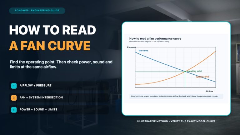
A useful fan duty combines airflow and pressure. Include the real resistance path: filters in their relevant condition, coils, guards, louvers, leakage assumptions, ducts, transitions, dampers and cabinets. Poor inlet approaches, abrupt transitions or nearby obstructions can also create system effects that a catalog curve does not represent.
Check full load, part load, alternate airflow routes, maintenance states and credible failure conditions. A control command cannot remove a physical restriction. The supplier question is not “Is this an AI fan?” but “Can this arrangement satisfy the documented system curve and control envelope across the cases we will test?”
Put axial and centrifugal choices in context
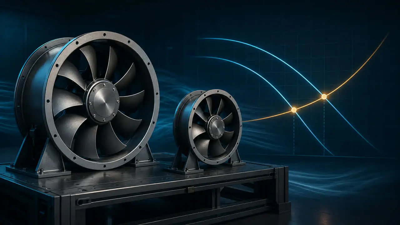
Axial and centrifugal designs move air differently, and neither label determines suitability on its own. Axial arrangements are often considered where a straight-through flow path and compact installation are useful. Centrifugal and plug-fan arrangements are often considered when equipment layout and the pressure path favor them. This guide to centrifugal and axial fan differences is a useful starting point, not a substitute for project data.
At facility level, a fan may sit inside air-handling equipment rather than beside computing hardware. The EC plug fan category offers a research path for plenum-style arrangements where the surrounding unit forms part of the air path. Where an axial path is being screened, the EC axial fan category is another research route. Neither category establishes project fit; final selection still requires current model and project data.
Make controls follow the condition that matters
A return-air temperature may describe one part of the system while missing a local rack-inlet problem. A differential-pressure target may support containment but still needs sensible sensor placement. Write the sequence in plain language: normal control variable, limits, sensor validation, communication-loss behavior, alarms, and the transition after a fan or another cooling component fails. Then verify that the selected fan and drive can follow that sequence across the required range.
Check redundancy in the failed state
Counting installed fans does not prove redundant airflow. When one unit in an array stops, the remaining operating point can shift, air may pass backward through the idle path, common pressure can change, and distribution across coils or branches may become uneven.
Define the unavailable component, its isolation method, the required remaining duty, applicable limits and failure detection. Verify that case using the actual array geometry and resistance path. Include maintenance isolation too: a system that is redundant on paper but cannot be serviced inside its operating boundary has unfinished operational analysis.
Compare energy across the same boundary
A fan power reading is not a complete comparison between cooling architectures. If an option transfers heat into a liquid loop, its pumps, coolant distribution equipment, controls and heat-rejection duties belong to the same accounting boundary. Compare the same heat load, ambient assumptions, availability requirement, inlet limits and schedule. Record what is included and excluded instead of attaching a broad savings claim to a technology label.
Turn selection into a verifiable specification
- Boundary: Name the server, rack, row, room, support-space or heat-rejection duty.
- Architecture: Map air and liquid heat paths and assign every residual load.
- Envelope: Define airflow and pressure for normal, part-load, alternate and failure modes.
- Resistance: Include filters, coils, dampers, cabinets, containment, ducts and installation effects.
- Controls: Document sensors, logic, limits, communication-loss behavior and recovery.
- Verification: Agree on the curves, inspections and staged tests used for acceptance.
Fans used in AI data centers are different only to the extent that their assigned duties are different. Keep the marketing label out of the acceptance criteria. Put the heat path, operating envelope, interfaces, control response, failure state and verification evidence in. That gives designers, operators and suppliers a common basis for deciding whether a particular fan arrangement belongs in the system.