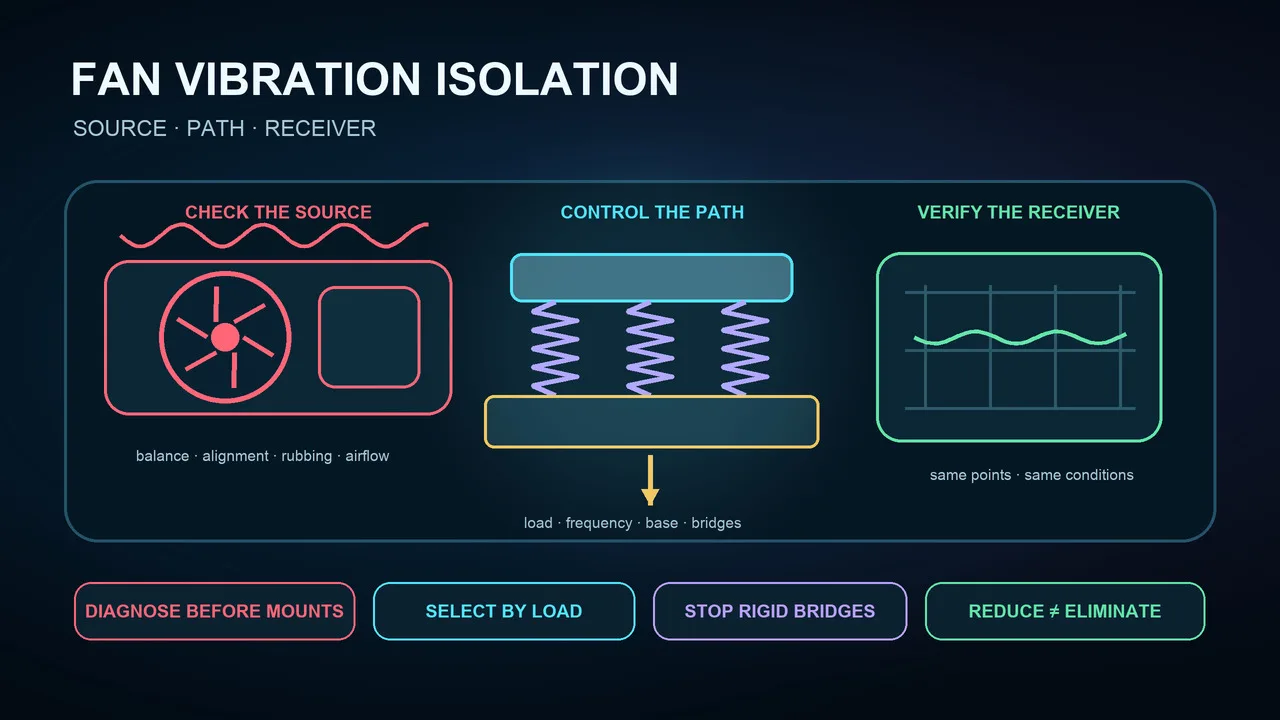
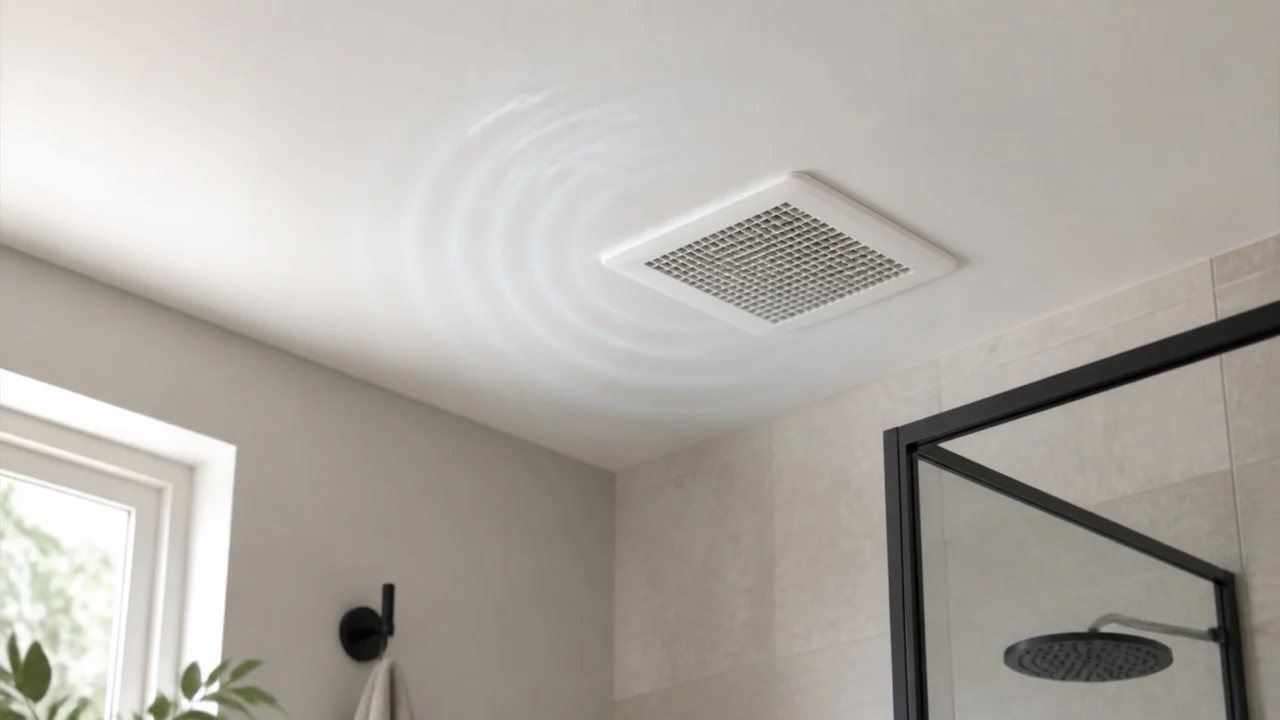
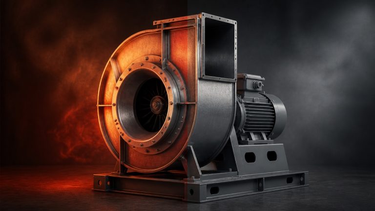
“Kill vibration” is a useful design ambition, but zero vibration is not a defensible commissioning claim. A fan vibration isolator is intended to reduce motion transmitted from the machine into a base, floor, curb, frame, or building. It does not correct an unbalanced wheel, damaged bearing, misalignment, rubbing, unstable airflow, loose hardware, or an inadequate structure.
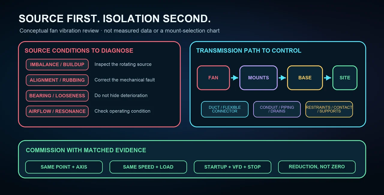
A reliable installation therefore starts with one decision: is the unwanted motion being generated by a fault at the source, or is acceptable machine motion finding an efficient path into the receiver?
Decide whether the fan or the transmission path is the problem
Inspect the fan before selecting a pad or spring. Record wheel condition, buildup, balance history, shaft and bearing condition, belt or coupling alignment, soft foot, looseness, contact marks, motor condition, inlet distortion, damper behavior, and the operating point. A mount can reduce transmission while a mechanical or aerodynamic defect continues to worsen.
Then trace every route from the machine to the occupied space or sensitive equipment. The main path may be the fan base, but ductwork, conduit, piping, drains, guards, access platforms, or a rigid restraint can bypass the isolators. A quiet fan casing with a noisy room elsewhere often points to a structural path rather than a simple fan fault.
Measure the operating condition before choosing a mount
Useful vibration data needs context. Identify the measurement point and axis, instrument and mounting method, units, bandwidth, fan speed, VFD setting, airflow condition, damper position, and system load. Compare measurements taken under the same conditions. A phone reading or a subjective “feels smoother” observation is not a substitute for a defined test.
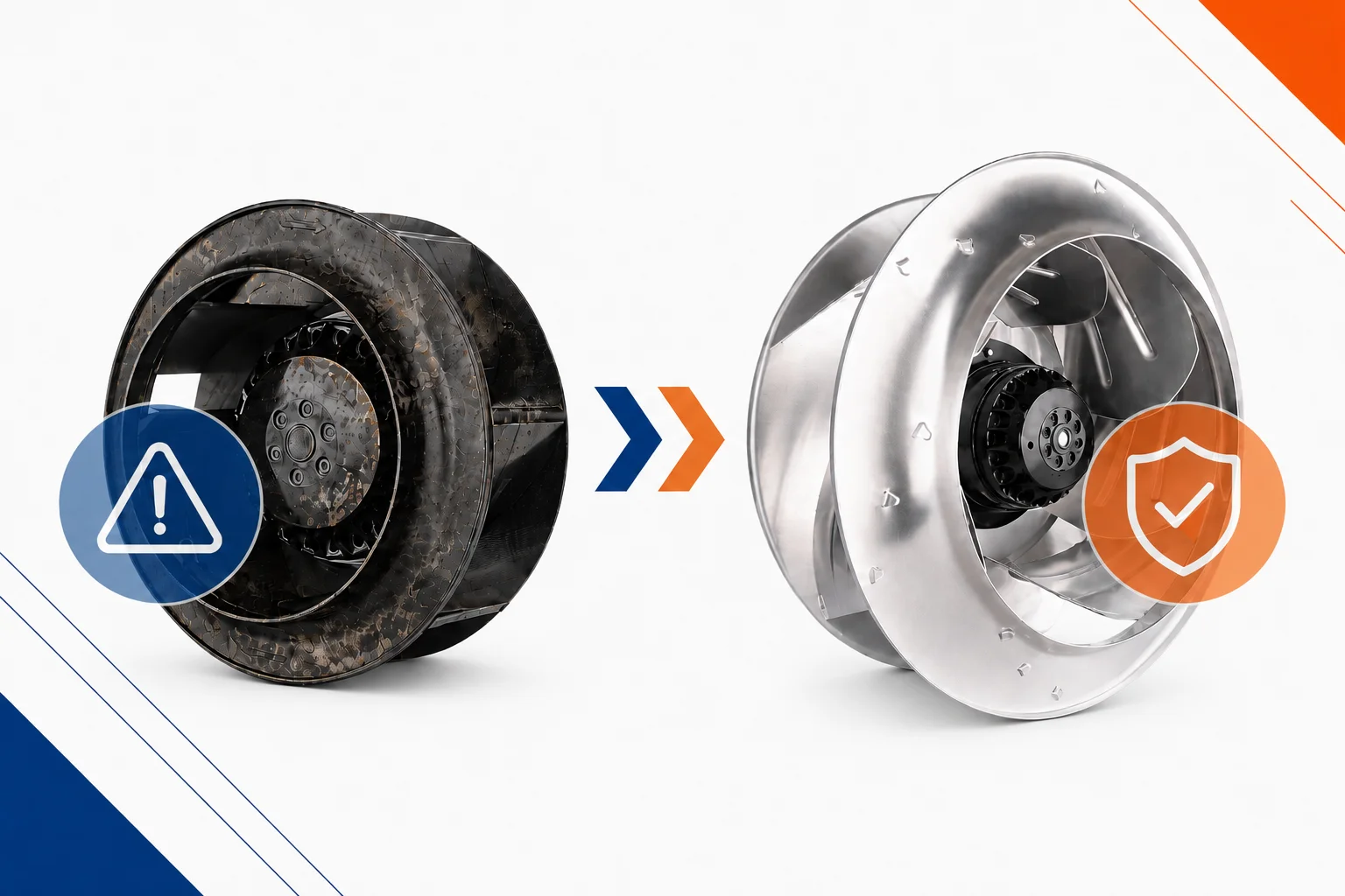
Frequency information helps separate rotational, blade-pass, belt, electrical, and structural behavior. If inspection points toward rotor imbalance, correct the source using an appropriate procedure; our centrifugal fan balancing guide provides additional context. Isolation should not be used to hide a condition that is still loading bearings, shafts, belts, or fasteners.
Select the isolator by frequency and actual supported load
Isolation is a frequency problem, not a visual choice between rubber and springs. The forcing frequency must be considered against the natural frequency of the supported fan, base, mounts, and structure, with damping and transient operating modes included. Near resonance, a softer support can amplify motion instead of reducing it. Startup, shutdown, and a VFD sweep may cross regions that steady operation avoids.
Do not divide nameplate weight by the number of mounts and assume each corner carries the same load. Center of gravity, motor position, base stiffness, drive arrangement, accessories, thrust, and dynamic forces can produce unequal reactions. Use an engineered load distribution, select every mount within its documented working range, and verify installed height and deflection rather than relying on color, appearance, or a universal rule.
Treat the base and supporting structure as part of the system
An isolator does not sit on an infinitely rigid floor. A roof curb, mezzanine, platform, suspended frame, light slab, or long-span member has its own stiffness and modes. If the support deflects or resonates, adding a softer mount may shift the problem without controlling it. Review strength, local stiffness, fatigue, anchorage, penetrations, access, and applicable wind or seismic demands with the responsible engineer.
The fan base also needs enough rigidity to distribute load without twist. Unequal mount height, soft foot, settlement, or a distorted base can change shaft, pulley, coupling, and seal alignment. Level and align at the correct installation stage, then check again after the equipment is loaded and the ductwork and utilities are connected.
Stop ductwork and services from bridging the isolation
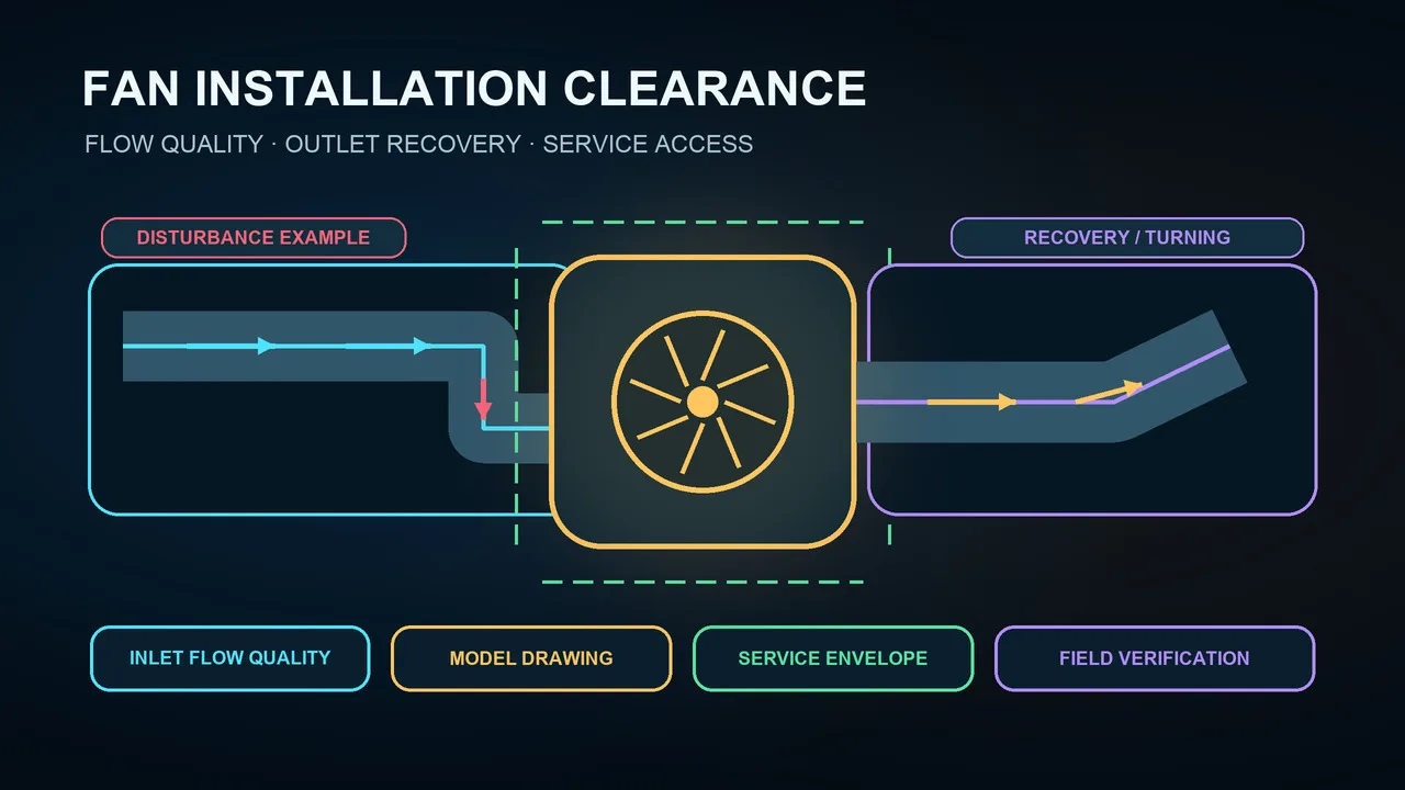
Every rigid connection around the fan can become a parallel spring. Ducts need independent support and alignment so they do not pull the casing or carry their weight through the fan. A flexible connector needs the correct free length, area, material, rating, and alignment; it should not be stretched tight, crushed, collapsed, or used to absorb a large offset.
Electrical conduit, control tubing, drains, hydronic or refrigerant lines, and accessories deserve the same review. Flexible sections and loops must comply with their own mechanical and electrical requirements. Maintain equipment grounding and bonding because rubber mounts and fabric connectors are not electrical bonding paths. Restraints and snubbers must allow normal isolation travel without continuous hard contact while still controlling abnormal movement.
Install the mounts safely without creating a new fault
Changing mounts may require lifting or jacking a heavy machine and handling stored spring energy. Confirm equipment weight, center of gravity, approved lifting points, rigging, jack and cribbing capacity, allowable travel, and the work sequence. Apply the site’s energy-control procedure, verify zero energy and rotation, and never work beneath suspended equipment or rely on hydraulic pressure alone.
Do not use an isolator bolt as a lifting point, put hands under an unsupported base, or adjust a spring, shim, alignment, or anchor while the fan is running. Restore every guard before operational checks. The broader inspection and safety sequence in our centrifugal fan operation and maintenance guide can help organize the surrounding work, but the exact equipment manual and approved site procedure remain controlling.
Commission every operating mode with matched measurements
Before startup, verify mount load, installed height or deflection, level, alignment, restraint clearance, base contact, flexible connections, independent supports, grounding, guards, and removed shipping blocks. Observe startup, intended VFD range, steady operating points, damper transitions, shutdown, and emergency modes from a guarded safe position. Check for excessive movement, contact, bottoming, or a connection that becomes taut.
Compare before-and-after vibration at the same points, axes, units, bandwidth, and operating conditions. Include the fan, base, supporting structure, and affected receiver. The defensible outcome is a documented reduction in transmitted vibration within the agreed scope—not “zero vibration” everywhere and not proof that every source fault has been corrected.
Prepare a useful fan isolation review package
- Machine: fan arrangement, speed range, motor and drive, operating point, weight, center of gravity, and approved lifting information.
- Symptoms: where motion or noise appears, when it changes, and matched measurement points, axes, units, and operating conditions.
- Support: base geometry, mount locations, corner reactions or load model, structure type, anchorage, and restraint requirements.
- Connections: duct, flexible connector, conduit, piping, drains, grounding, accessories, and independent supports.
- Verification: source-fault inspection, installed mount condition, startup and VFD behavior, and before-and-after results.
This information lets an engineer or supplier distinguish a machine repair from a transmission-control problem and select a mount within a documented load and frequency boundary.