Meeting the Envelope for a Drop-In Impeller Replacement
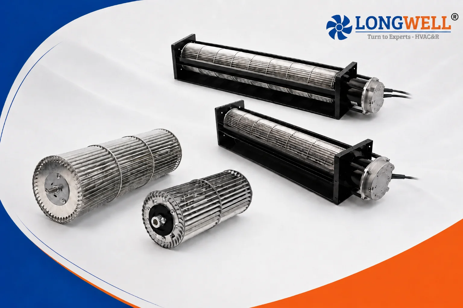
The customer needed a drop-in impeller replacement for a failed rotor. They run a commercial air curtain over a busy door. Their original rotor failed, so a drop-in impeller replacement was the only route that left the chassis alone. So a drop-in impeller replacement has to match the chassis exactly.
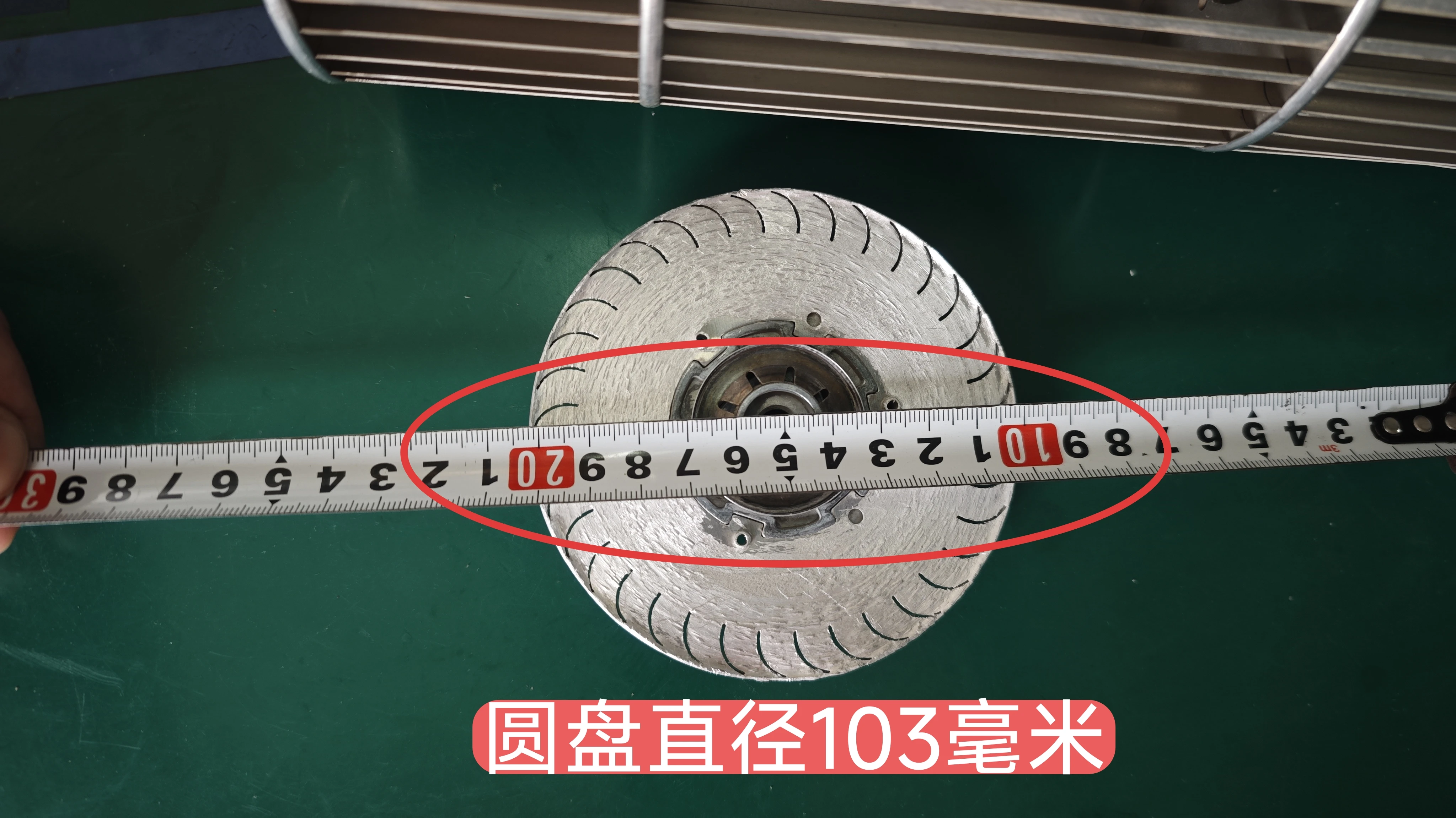
The envelope was fixed and not open to discussion. Its blade length had to be exactly 685 mm. Meanwhile the outer profile had to sit within 100 mm. Furthermore, the motor interface demanded an exact match.
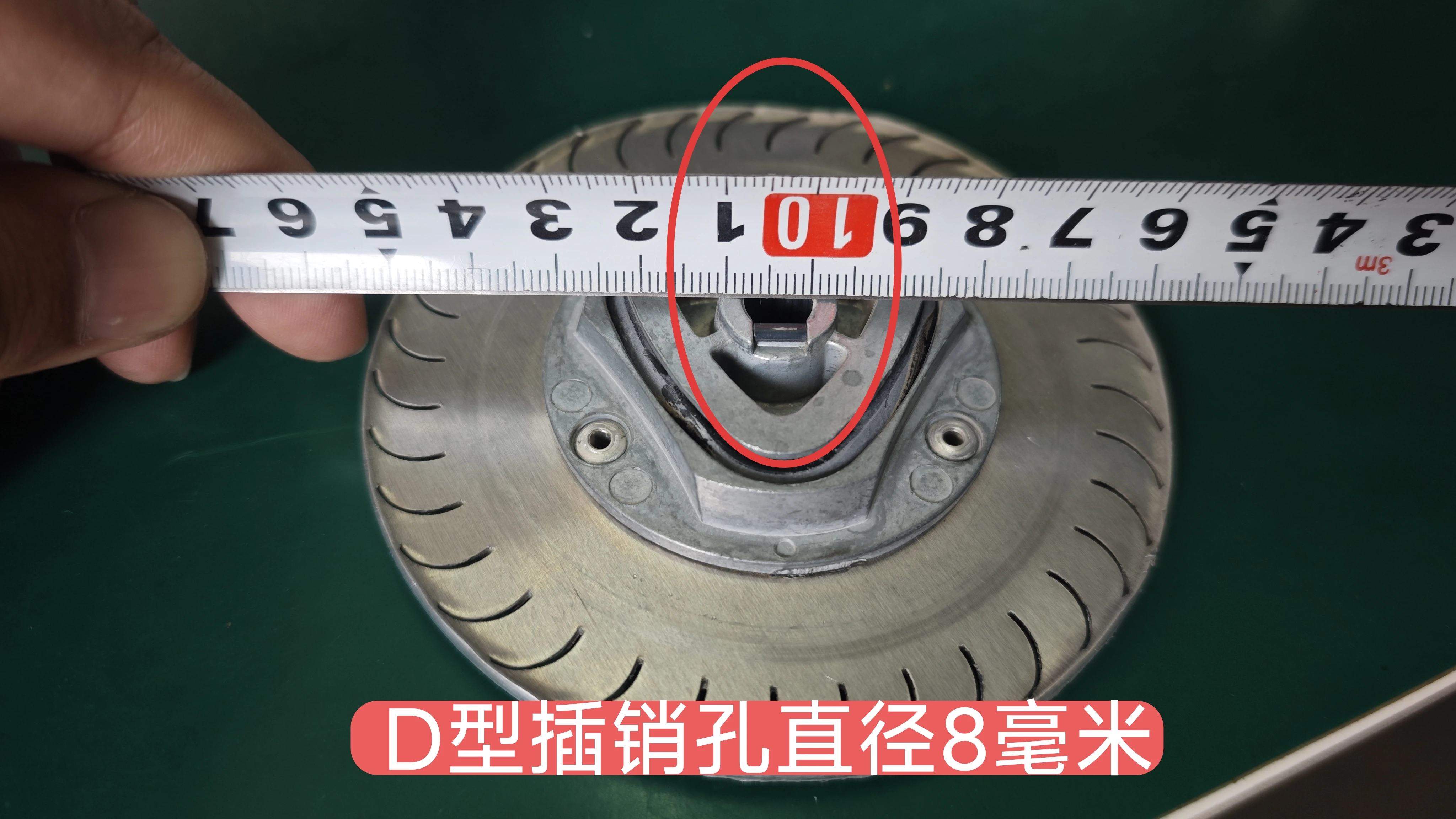
The existing direct drive uses an 8 mm shaft. The new hub needed an 8 mm bore with a specific D-cut profile to connect securely. Noise limits were another hard constraint. The equipment runs continuously.
Also, it runs at 1500 RPM to seal the door. Therefore, small imbalance across the 685 mm span makes a lot of noise. Bearing failure follows soon after. Furthermore, the customer sent photos and precise tape measurements.
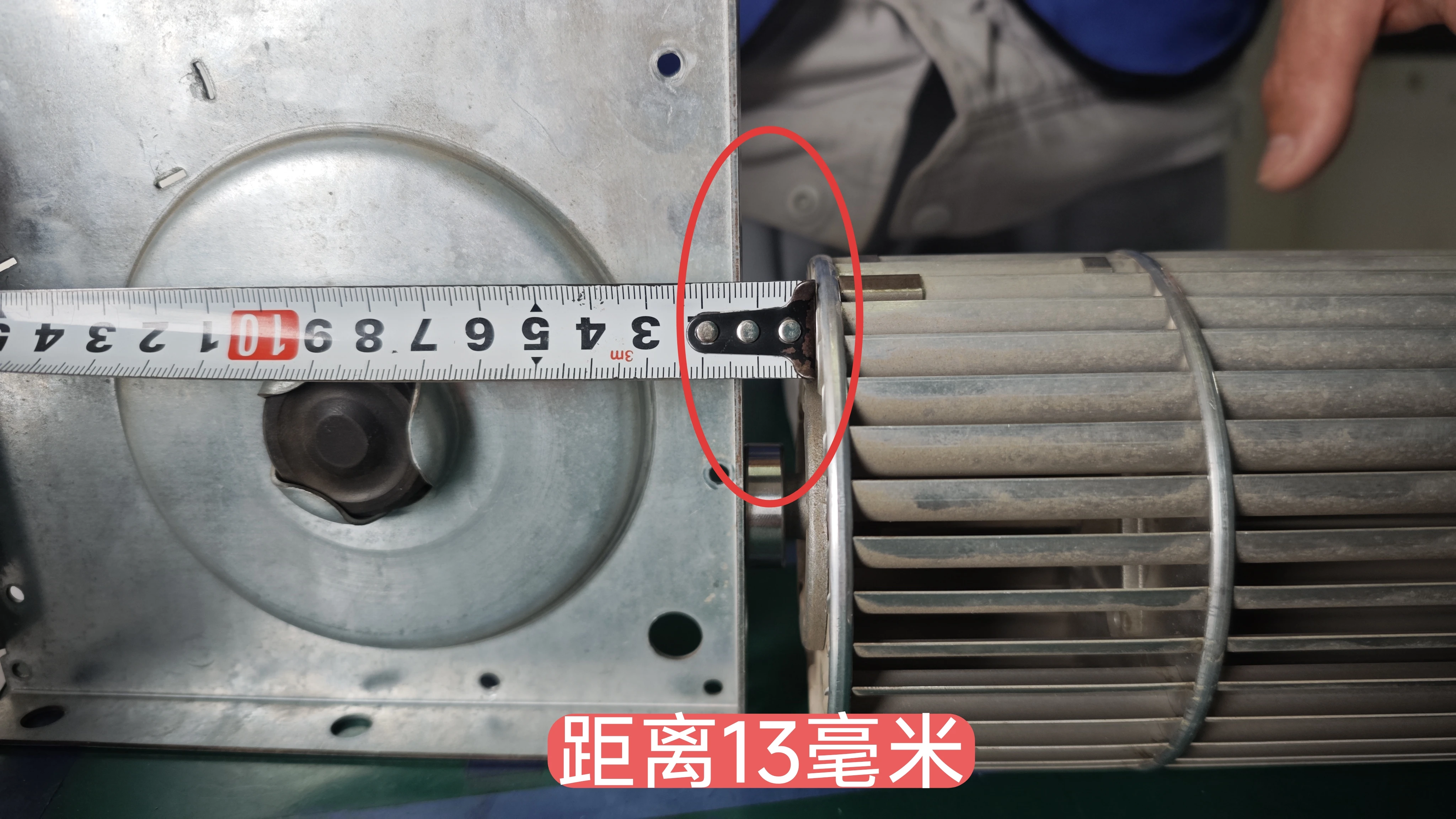
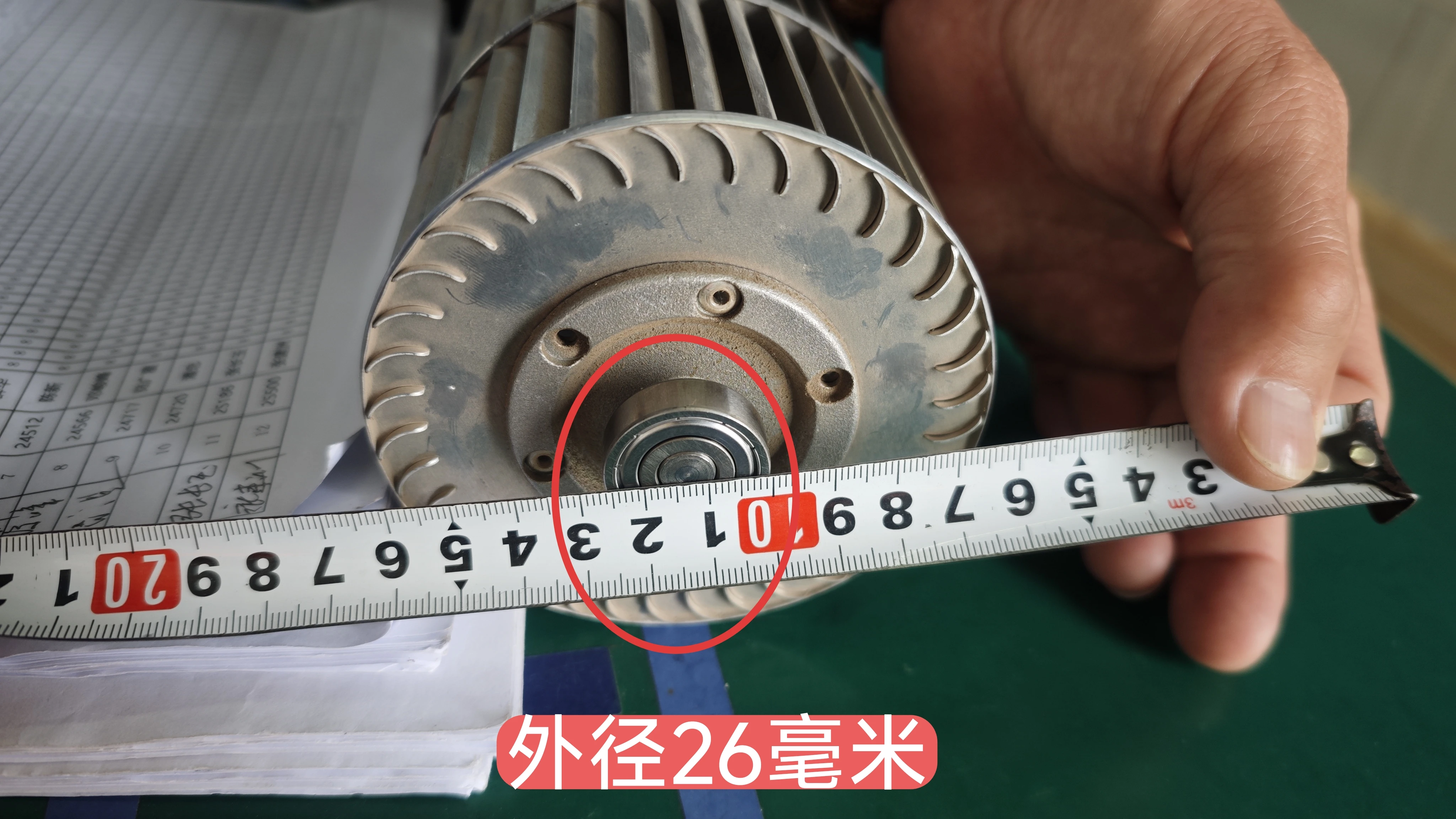
We reviewed the failed original component. The new rotor had to match the mounting hardware flawlessly. Specifically, we needed to fit the 26 mm outer hub diameter. We also had to accommodate the 13 mm shaft pin extension. Finally, the finished part must suit UL 507 limits for motor-operated fans.
Engineering the Drop-In Impeller Replacement
We had to choose the right blade material first. Extruded plastic offers a materially lower cost. It also speeds up the production cycle. However, we rejected plastic for this 685 mm footprint.
A standard plastic rotor deforms outward under high centrifugal loads. The 1500 RPM test speed forces the plastic to bow. Instead, we selected 5052 H34 aluminum. We formed 40 individual blades from this specific temper.
It delivers superior tensile strength. Meanwhile, the total rotating mass remains low enough for the OEM motor. By contrast, a heavier steel alloy would draw too much current. It would overwhelm the existing drive circuit.
Supporting the Extended Span
Next, we focused on structural stability. Long rotors naturally suffer from midpoint deflection at high speeds. We integrated eight intermediate center plates to prevent this bowing. These sit evenly along the whole length.
Each plate is cut from 3003 H24 aluminum. Securing 40 aluminum blades to eight plates demands tight precision. So we fixed the inner parts with strong stainless steel rivets. This method requires significantly more assembly time than a welded design. Even so, it holds the middle plate radial runout strictly under 0.5 mm.
Balancing the Hub Assembly
Finally, we built the end mounting hubs to fit the customer’s D-type pin hole. We machined the critical bore to a strict 8 mm (-0.008 to -0.012 mm). This negative tolerance guarantees a firm interference fit. We then dynamically balanced the completed metal cross flow impeller at 1500 RPM.
The standard requires residual unbalance to stay below 300 mg. As a result, the design holds airflow steady and keeps shake out.
Technical Specifications
| Impeller Outer Diameter | 100 mm (102 mm max plate diameter) |
| Overall Length | 685 mm (± 1 mm) |
| Blade Count | 40 |
| Blade Material | 5052 H34 Aluminum |
| Center Plate Material | 3003 H24 Aluminum |
| Hub Bore Diameter | 8 mm (-0.008 / -0.012 mm) |
| Hub Outer Diameter | 26 mm |
| Shaft Pin Extension | 13 mm |
| Test Speed | 1500 RPM |
| Max Residual Unbalance | < 300 mg |
| Middle Plate Radial Runout | < 0.5 mm |
The strict hub bore tolerance (-0.008 to -0.012 mm) is the most critical row here. A loose fit on the 8 mm shaft introduces an immediate mechanical rattle.
Reference: ISO 21940 covers the test method behind these figures.
Technical Documentation
The first photo verifies the 8 mm bearing seat thickness on the original component.
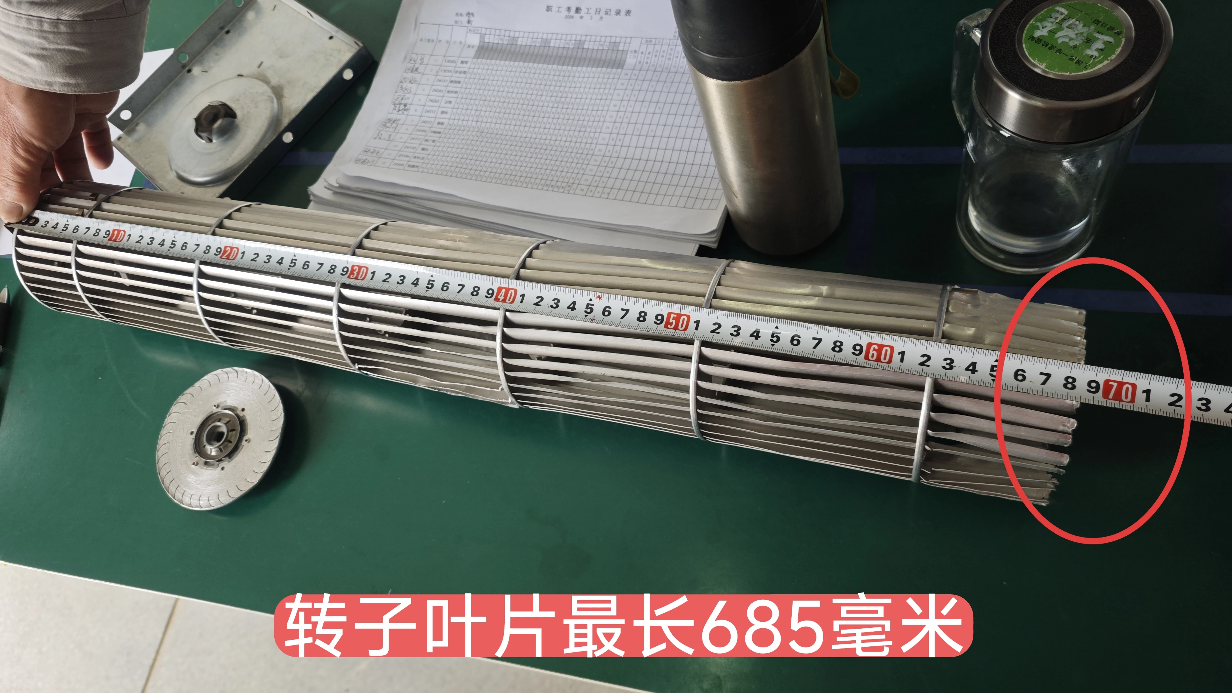
Next, we confirm the strict 685 mm overall blade span needed for the chassis.
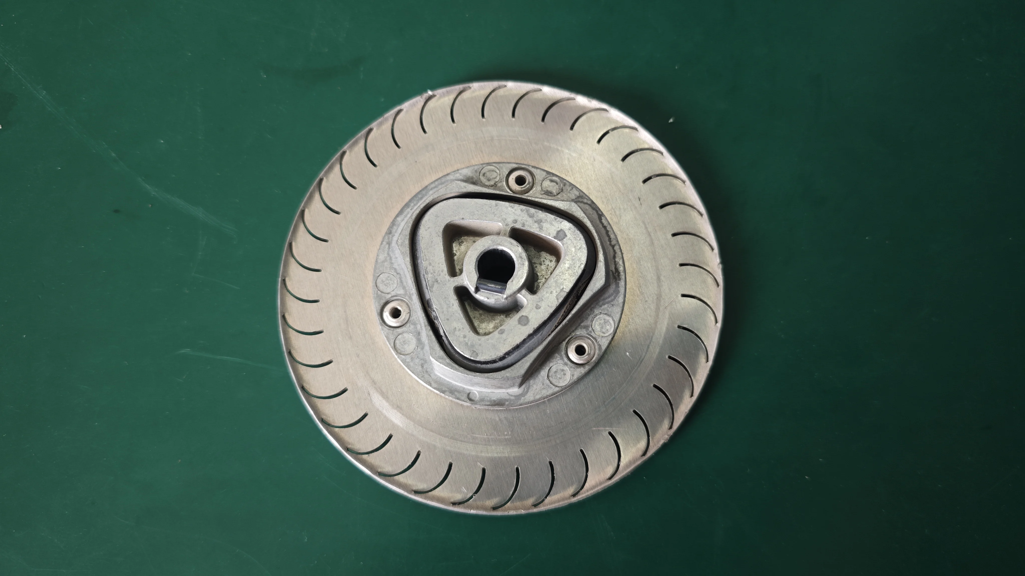
A detailed view highlights the D-shaped hub interface linking the OEM motor.
Download the Technical Drawing (PDF)
Our drawing lists the 40-blade build, the materials, and dynamic balancing targets.
Specifying a Drop-In Rotor Assembly
Measure the damaged rotor exactly before you ask for a quote. A small dimensional error ruins the entire part.
- First, measure the true outer diameter of the end plates. You cannot simply measure the curved blades. A clearance error of just 2 mm forces the wheel to scrape the housing.
- Second, check the mechanical shaft interface on both ends. You must explicitly identify the motor connection. Find out if it uses a round bore, a keyed D-cut, or an internal bearing.
- Always identify the maximum operating speed. A custom wheel balanced for 900 RPM vibrates violently if an HVAC motor drives it at 1500 RPM.
- Finally, send clear reference photos showing a tape measure held against the old hub. That way the first drawing matches what you really have. If your application demands tight tolerances, we test rotor balance to AMCA methods directly in our Ningbo facility.
Related: Cross Flow Fans.
Common Engineering Questions
Technical Documentation & Resources
Browse our axial fans range, the AC axial fans section, or EC axial fans.
Have a Similar Fan Requirement?
Longwell’s engineering team delivers custom spec sheets and samples within 90 days. Since 1990, we have supplied EC fans and blowers to OEMs across HVAC, cold chain, data center, and industrial applications worldwide.
Browse Related Products:
🏆 ISO 9001 / ISO 14001 / ISO 45001 | CE (TÜV) | UL/ETL | ATEX Zone 21/22 | AMCA 210-16 / ISO 5801 tested