The Air Curtain Constraints
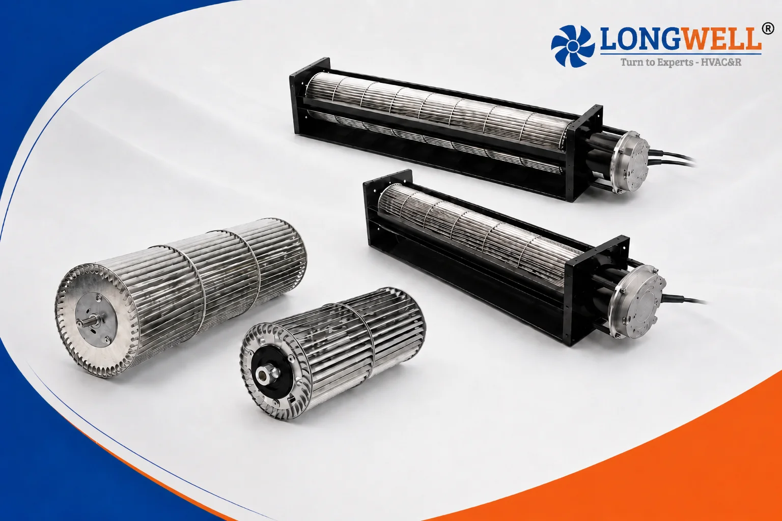
A buyer needed a custom fan part. They requested a exact 90mm cross flow impeller for a new air curtain. First, the unit had to fit a very tight space. The design demanded a total length of 600 mm.
Next, the outer diameter had to measure exactly 90.5 mm. Also, the steel shaft required a strict 6 mm size. Meanwhile, the inner sleeve bore needed an exact 8 mm fit. So, we could not just pick a stock fan from a list.
We had to build a brand new tool. Because air curtains run in busy shops, noise limits are very tight. The fan must run smoothly all day. Therefore, the long rotor needed strict runout controls.
Radial runout had to stay perfectly under 0.7 mm. Axial runout could not exceed 0.6 mm. Finally, shaft runout had to remain strictly under 0.2 mm. These strict limits stop the long plastic tube from bowing or shaking.
Even so, spin balance targets proved just as strict. The buyer wanted a remaining unbalance below 0.3 g. They check this balance at a 1200 RPM test speed. Also, the rotor had to pass a hard speed test at 1600 RPM.
They required no odd sound at this top speed. So, the design team had to choose the right raw plastics and joint methods. We had to hit all these precise numbers without driving up the final part cost.
Designing the Fan and Choosing Plastics
We faced several hard choices to meet these strict goals. First, we looked at the base plastic for the fan blades. A standard plastic like ABS costs much less. However, standard ABS bends too easily over a wide 600 mm gap. Instead, we picked AS+GF30% material for this project. This blend mixes Acrylonitrile Styrene with a 30% glass fiber fill. The glass fiber makes the plastic very stiff. So, the long fan blade will not sag over time. Also, this stiff plastic helps us meet the strict 0.7 mm radial runout limit. The trade-off was a much longer mold cycle time. We had to cool the hot plastic very slowly. This slow cooling stops the long parts from warping in the mold. It increased the build time, but it ensured perfectly flat parts.
Joining the Plastic Segments
Next, we had to connect the long plastic sections together. Some makers use liquid glues to join fan blades. We rejected liquid glue right away. Glue adds random, hidden weight to the blade joints. Thus, glue ruins the tight 0.3 g balance target instantly. Instead, we chose “noise wave” welding. High-frequency sound melts the plastic edges directly together. This method adds zero extra weight to the part. Also, it creates a very strong bond with no false welds. The finished joints look smooth and have no plastic burrs. This strong bond ensures the fan survives the 1600 RPM speed test without cracking. The downside was the high first cost of the custom sound welding horns. Even so, the perfect balance results made the extra setup cost worth it.
Hitting the Balance Targets
Finally, spin balancing required special design care. The buyer rule stated we could use no more than three balance weights. We achieved this strict limit by making the injection molds very precise. Precise molds mean the plastic parts come out naturally balanced from the start. So, we only add tiny metal clips at the very end to hit the 0.3 g limit. This limits airflow blocks and keeps the air curtain very quiet. Lastly, we paint the final part black to match the exact housing design.
Technical Specifications
| Part Number | LWPI-φ90.5*600-05 |
| Impeller Dimensions | φ90.5 mm x 600±2 mm |
| Shaft Diameter | φ6 -0.01/0 mm |
| Sleeve Inner Bore | φ8 +0.022/0 mm |
| Material | AS+GF30% (Black) |
| Rotation Direction | Counter-Clockwise (CCW) |
| Max Test Speed | 1600 RPM |
| Balance Target | < 0.3 g at 1200 RPM |
| Max Balance Weights | ≤ 3 pcs |
| Radial Runout | < 0.7 mm |
| Axial Runout | < 0.6 mm |
| Shaft Runout | < 0.2 mm |
First, you should look closely at the runout rows. The 0.2 mm shaft runout limit directly dictates how long the motor bearings will last. Next, notice the very strict balance target. Keeping the unbalance below 0.3 g makes sure the 90mm cross flow impeller runs quietly at 1200 RPM. Finally, the AS+GF30% choice gives the long part its needed stiffness. So, the fan hits the 1600 RPM max test speed safely without breaking.
Reference: ISO 21940 covers the test method behind these figures.
Technical Documentation for the 90mm Cross Flow Impeller
First, the main drawing shows the exact runout limits and the welding rules for this new fan rotor.
LWPI-φ90.5X600-05 Engineering Drawing (PDF)
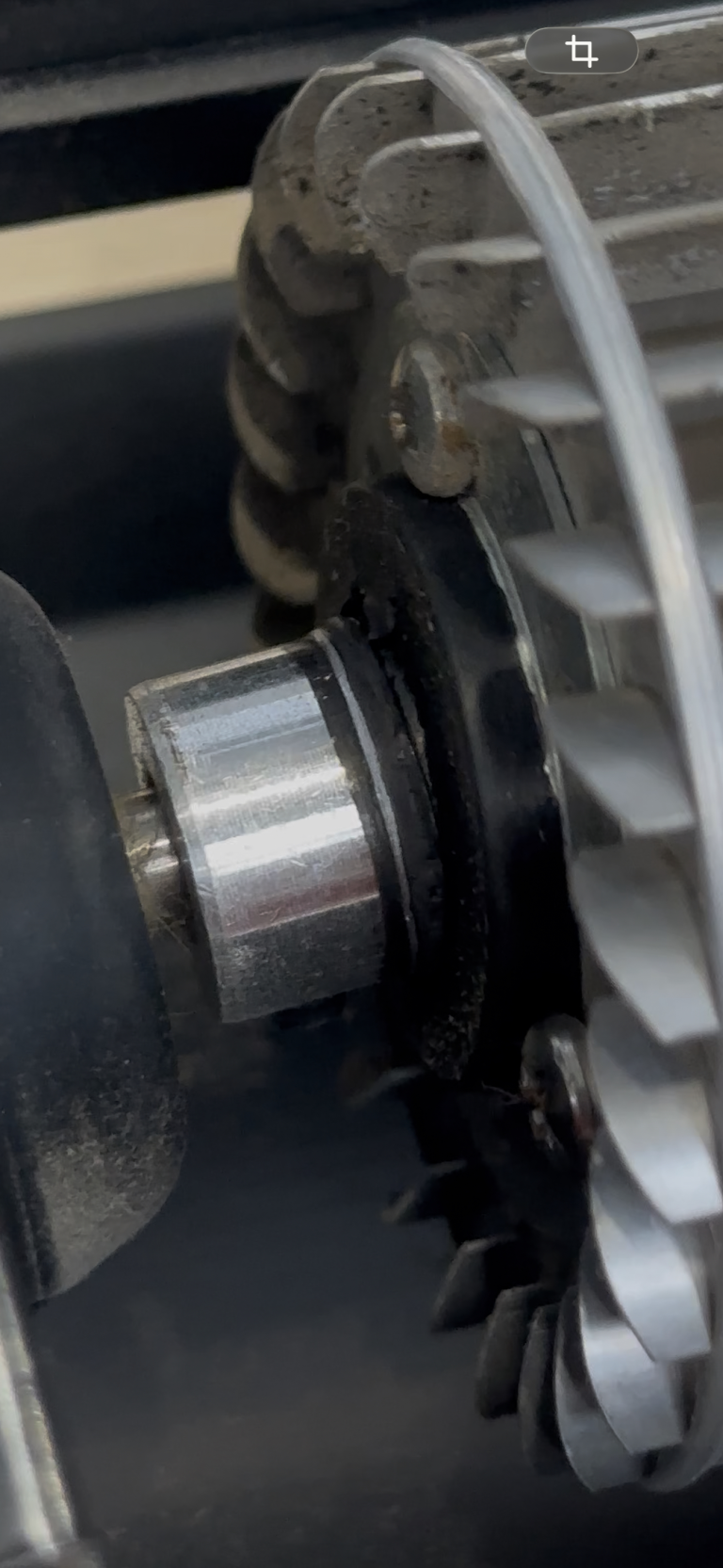
Then, we use a precise tool to check the 6 mm steel shaft before final build.

Finally, we verify the 8 mm inner sleeve bore to ensure a perfect motor fit.

Specifying a Long Cross Flow Fan
If you face a similar design challenge, you must check several key details before you order parts.
- First, you should measure your exact space limits. A long 90mm cross flow impeller needs very tight spaces to fit your housing. You must verify the shaft and sleeve sizes.
- Next, clearly state your acceptable runout limits. A long plastic rotor bends easily in the middle. Therefore, defining a strict radial runout stops the plastic blades from scraping the metal fan housing.
- Also, you must choose your base plastic carefully. Cheap plastics will warp over a long 600 mm span. Instead, you should pick a stiff blend like AS+GF30%. This strong blend easily supports high test speeds like 1600 RPM.
Related: Cross Flow Fans.
Common Fan Design Questions
Technical Documentation & Resources
Browse our cross-flow fans range, the AC cross-flow fans section, or cross-flow impellers.
Have a Similar Fan Requirement?
Longwell’s engineering team delivers custom spec sheets and samples within 90 days. Since 1990, we have supplied EC fans and blowers to OEMs across HVAC, cold chain, data center, and industrial applications worldwide.
Browse Related Products:
🏆 ISO 9001 / ISO 14001 / ISO 45001 | CE (TÜV) | UL/ETL | ATEX Zone 21/22 | AMCA 210-16 / ISO 5801 tested