Matching a Specific Footprint in a Commercial AHU
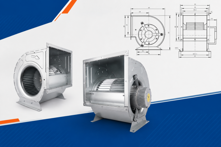
First, an HVAC engineer contacted us for a replacement air moving component. Specifically, they needed a 160mm centrifugal impeller to fit an existing dual-shaft motor. This motor powers a commercial air handling unit. Because the central motor drives two separate fan decks, the wheels must mirror each other.
Therefore, the customer required one clockwise wheel and one counter-clockwise wheel. Furthermore, the physical envelope was extremely tight. The outer diameter could not exceed 160 mm. Meanwhile, the total height had to be exactly 76.7 mm.
This specific dimension matches their existing volute housing perfectly. Next, the motor shaft bore was strictly fixed at 8 mm. This strict limit prevents mechanical vibration at high operating speeds. Finally, the expected production volume was quite modest.
The customer requested just 350 units per quarter for each rotation direction. They also needed one sample of each before mass production. Consequently, tooling a completely custom size would destroy the project budget. Instead, we needed to adapt an existing geometric profile.
Also, the application requires performance testing TO AMCA 210-16 standards. This step ensures the new air volume matches the original specifications exactly.
Evaluating Tooling for a 160mm Centrifugal Impeller
First, we faced two distinct options for delivering this mirrored 160mm centrifugal impeller setup. We could build a brand new mold for the exact 160x75mm dimension. However, custom tooling demands massive upfront capital. For a small run of just 350 pieces per quarter, that route carried a materially higher cost per unit. Therefore, we rejected the custom mold idea quickly.
Instead, we looked at our existing tooling inventory. We already produce forward-curved wheels with a 160 mm outer diameter. Specifically, our standard model RD160X75 matched the required 76.7 mm height perfectly. Furthermore, it matched the 73.5 mm inner blade height exactly. By contrast, a new design would take weeks to develop. So, reusing this geometry saved both time and money.
Adapting the Standard Hub
By choosing the standard mold, we avoided tooling charges completely. Meanwhile, we still had to solve the center bore problem. The customer needed an 8 mm center bore to fit their direct drive shaft. We machine the central hub insert separately from the main wheel.
Consequently, we could easily press-fit an 8 mm bore into the standard base. However, every engineering choice involves a specific trade-off. Here, the trade-off involved total weight against lead time. A custom mold could create a slightly lighter wheel.
By contrast, adapting the standard metal hub adds marginal rotational mass. Consequently, the motor draws slightly more current during startup. Even so, the customer accepted this minor electrical penalty. It allowed us to ship a sample from stock within 3 days.
Next, standard mass production takes just 15-30 days. Finally, we generated two distinct part numbers for the factory. Part LWF-φ160*75-01 spins in the counter-clockwise direction. Next, part LWF-φ160*75-02 spins in the clockwise direction.
Both wheels maintain the strict 140 mm inner ring diameter. This dimension is completely necessary for the existing scroll housing.
Technical Specifications
| Parameter | Specification |
|---|---|
| Model No. (CCW) | LWF-φ160*75-01 |
| Model No. (CW) | LWF-φ160*75-02 |
| Outer Diameter (Dim) | 160 mm |
| Inner Blade Height (A) | 73.5 mm |
| Total Height (B) | 76.7 mm |
| Inner Ring Diameter (D1) | 140 mm |
| Inner Diameter (D2) | 132.7 mm |
| Shaft Bore (D4) | 8 mm |
First, the total height and the shaft bore represent the binding constraints for this project. Matching the exact 76.7 mm height ensures the wheel clears the housing. Furthermore, the 8 mm shaft bore demands precise machining to avoid runout. Next, maintaining the 140 mm inner ring diameter ensures the inlet cone fits properly. Finally, separating the parts by rotation direction prevents assembly errors on the factory floor.
Reference: AMCA 210 covers the test method behind these figures.
Technical Documentation
First, the LWF-φ160×75-01 Technical Drawing specifies the dimensional tolerances for the counter-clockwise impeller. It details the exact measurements required to match the customer’s volute. Next, the LWF-φ160×75-02 Technical Drawing provides the identical dimensional constraints mirrored for clockwise rotation. This sheet helps incoming quality inspectors verify the rotation direction before assembly. Finally, the  chart details the standard mold geometries available for adaptation. Engineers use this visual reference to confirm which standard wheel clears their housing without tooling costs.
Specifying Impellers for Dual-Shaft Motors
First, measure your existing volute clearance carefully before ordering. The most common mistake engineers make is ignoring the inner ring diameter.
* Always verify the total wheel height against the maximum insertion depth. A fan wheel that is two millimeters too tall will scrape the inlet ring.
* Next, specify the exact motor shaft bore diameter and the required tolerance. An 8 mm bore needs precise machining to meet
ISO balance grades and prevent wear.
* Furthermore, clearly indicate the required rotation directions from the motor drive end. A forward-curved geometry only generates static pressure efficiently when spinning properly.
* Finally, always check if an existing tooling profile can meet your physical envelope. Finding an off-the-shelf 160mm centrifugal impeller materially lowers your project cost. It also cuts custom NPI times down to standard 15-30 day production lead times.
In short, matching the mechanical dimensions is the binding constraint before any aerodynamic testing begins. Therefore, verify your physical limits first.
Related: HVACR Components.
Engineering FAQs
Technical Documentation & Resources
Browse our centrifugal fans range, the backward-curved fans section, or forward-curved fans.
Have a Similar Fan Requirement?
Longwell’s engineering team delivers custom spec sheets and samples within 90 days. Since 1990, we have supplied EC fans and blowers to OEMs across HVAC, cold chain, data center, and industrial applications worldwide.
Browse Related Products:
🏆 ISO 9001 / ISO 14001 / ISO 45001 | CE (TÜV) | UL/ETL | ATEX Zone 21/22 | AMCA 210-16 / ISO 5801 tested