
Air-Side Fan Integration for Data-Center Cooling Equipment
Integrating fans into data-center air-handling equipment requires more than matching nominal airflow. Define the coil and filter resistance, inlet geometry and control behavior for the proposed assembly. Where a fan array is considered, state the required operating conditions with every module running and with a module unavailable.
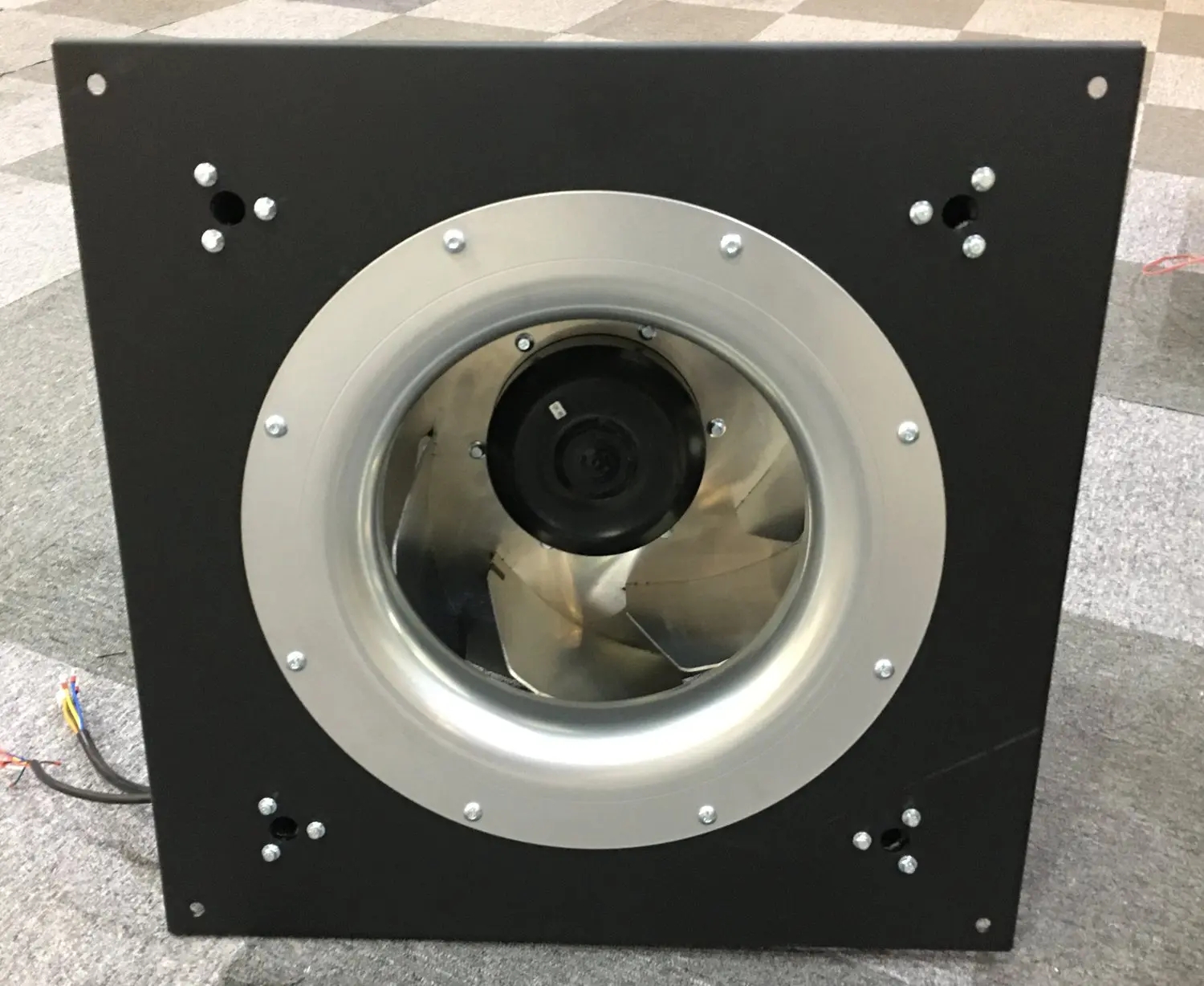
Prepare the air-side assembly for configuration review
This page focuses on fan integration inside CRAH/CRAC units and other data-center air-handling equipment. It supports reviews of installation space, control interfaces and service arrangements. The wider cooling architecture, liquid distribution equipment and facility-level energy or availability outcomes require their own system design and evidence.
Establish the installed airflow and pressure range
Provide the equipment airflow requirement and resistance through coils, filters and connected distribution paths. Include expected operating changes and service-limit conditions. Review the inlet ring, neighboring surfaces and discharge arrangement so the selected curve can be assessed against the actual installation rather than an unrestricted test setup.
- Coil/filter and distribution-path resistance
- Normal and service-limit operating points
- Inlet ring, obstructions and discharge geometry
Define commands, feedback and degraded operation
List the required speed command, monitoring signals and controller sequence for each fan. For an array, define the airflow or temperature conditions required when one module stops, together with any backflow control. Verify the remaining fans and controller response at that condition; parallel placement alone does not prove redundancy.
- Signal definition and controller responsibility
- Module-unavailable duty and backflow assessment
- Fault indication and remaining-fan response
Plan service access and acceptance records
Review how a fan module is isolated, removed and replaced within the installed unit. Confirm the mounting, wiring and access arrangements, then agree the sample or installation test conditions. Keep the complete configuration with measured airflow, power and sound results so any comparison can be assessed on a consistent basis.
- Isolation, access and replacement route
- Complete fan/motor/control configuration
- Defined airflow, power and sound test conditions
Match the fan family to the equipment.
Compare the proposed model at the required airflow and pressure, then check the installation and control interface.
Panel-mounted centrifugal options
Review panel-mounted centrifugal options where the inlet-ring and mounting arrangement suit the unit. Confirm the operating range, controls and module-unavailable requirements with the integrator.
Explore this fan family →
RLM centrifugal assemblies
Review complete centrifugal assemblies where motor access and mounting-frame geometry fit the air-handling unit. Confirm dimensions, selected duty and service requirements for the complete model.
Explore this fan family →Product images show family configurations. Request the drawing, curve and electrical information for the exact model being considered.
What should your fan enquiry include?
Share these application details so the fan proposal can be reviewed against your equipment.
Bring the equipment context to the fan review.
A drawing, the operating condition and a clear control requirement make the proposed configuration easier to compare. For a replacement, include the existing nameplate and wiring details.
Discuss your application →Reference material for the next step.
Compare assembly formats, then request the complete model drawing and duty data for the proposed air-handling unit arrangement.
Series catalog · PDFEC backward-curved fan catalog ↗Review centrifugal component options where a custom inlet and mounting assembly is planned; confirm the exact curve and configuration.
Engineering checklistFan replacement and controls checklist ↗Document mounting, electrical supply and controller interfaces before integrating or replacing fans within existing room-cooling equipment.
Catalogs support initial selection. Confirm the current specification and approved configuration with the project team.
What must be checked before describing an array as redundant?
Specify the required duty with a module unavailable, then assess the remaining fan capacity, backflow paths, power supply and controller response. Verify that condition in the intended equipment arrangement. The presence of several parallel fans does not by itself establish the required system availability.
Can an existing project saving be applied to a new unit?
A saving depends on the original equipment, operating point, control strategy and hours in each state. Use a documented baseline and a comparable proposed configuration for the new unit. Retain measured or supported power data and state the assumptions before estimating any project-specific benefit.
Continue with the equipment you are designing.
Share your equipment and operating conditions.
Send the drawing, target duty and project timing. Add the existing fan details when you need a replacement.