Fan installation clearance is not one universal distance. The space at the inlet affects how air approaches the fan, while the outlet connection affects turning and pressure recovery. Service access, electrical workspace, guarding, structure, weather protection, and fire or smoke provisions are separate requirements. A layout is only complete when each function has been checked.
This guide explains the review sequence without prescribing a generic diameter multiple. The exact fan arrangement, tested connection, manufacturer drawing, project specification, and applicable codes remain controlling.
Define which clearance the drawing is showing
Start by labeling every space around the fan. Is it an aerodynamic approach zone, a discharge-recovery connection, a motor-removal path, access to bearings or belts, electrical working space, a lifting route, or a fire and weather requirement? These zones can overlap physically, but they are not interchangeable.
A longer duct section does not replace guard-removal access. A wide service aisle does not guarantee uniform inlet flow. Likewise, moving a damper for airflow cannot override its listing, access, or smoke-control function. Writing the purpose beside each dimension prevents one convenient number from being used to answer several different engineering questions.
Begin with the fan’s rated connection and exact arrangement
Published performance comes from stated test configurations. Before reviewing the room or duct, record the fan type, size, rotation, discharge orientation, inlet cone or bell, connection arrangement, speed, air density, and selected operating point. Then compare the field layout with the manufacturer drawing and the condition represented by the curve.
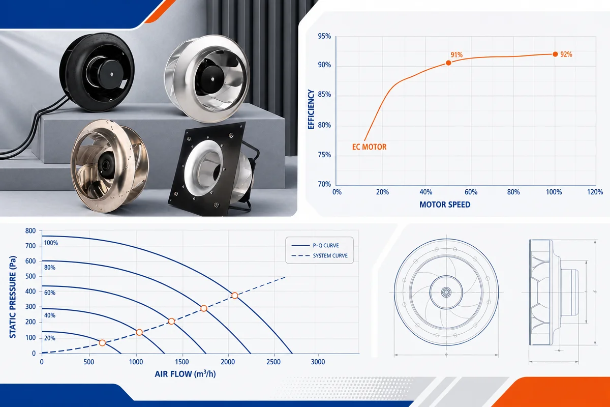
A catalogue curve is not a promise that every nearby elbow, wall, screen, transition, or plenum will behave like the test airway. For a practical explanation of how airflow and pressure appear on the chart, see our centrifugal fan curve guide. The curve is the baseline; the installed system still needs verification.
Protect inlet flow quality, not just empty space
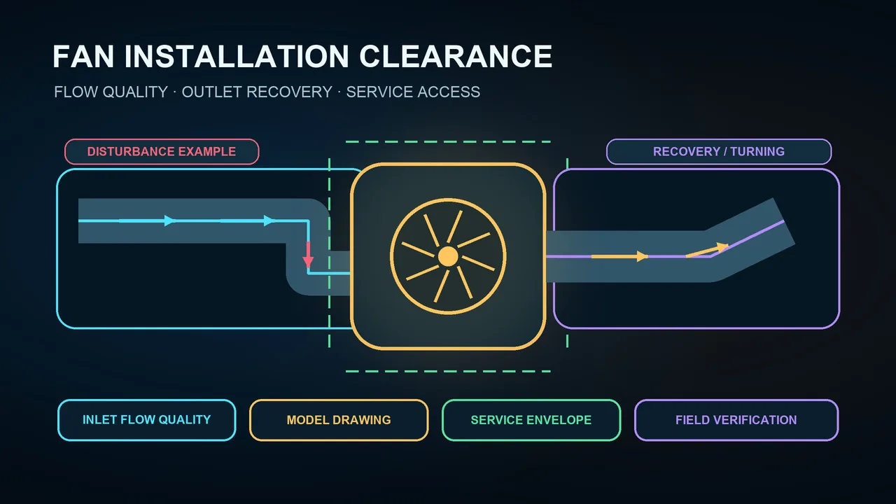
Air should reach the inlet without severe blockage, asymmetry, or uncontrolled pre-swirl. A nearby wall, elbow, filter frame, silencer, screen, splitter, damper, or abrupt plenum can crowd one part of the inlet even when a tape measure seems acceptable. The effect depends on fan geometry, velocity, rotation, and the shape of the surrounding connection.
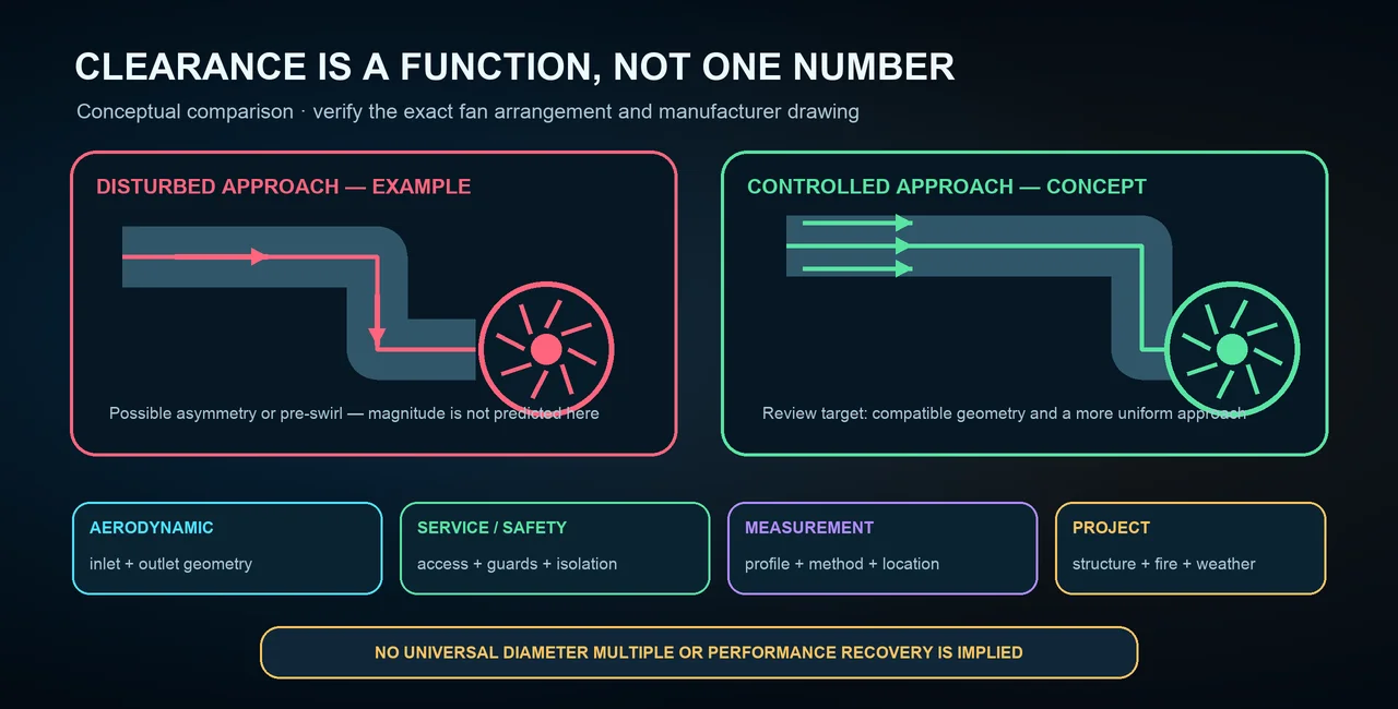
The illustration compares flow patterns conceptually; it is not CFD, measured data, or a spacing rule. Use the exact model drawing to decide whether the inlet needs a bell, transition, turning treatment, plenum change, or relocation. Never remove a guard or screen to improve airflow. If a protective device adds loss, include the approved device in the system calculation and selection.
Treat the outlet as a recovery and turning problem
Flow leaving a fan can have high velocity, swirl, and an uneven profile. An abrupt expansion, sharp elbow, offset transition, damper, coil, splitter, or obstruction can add loss and noise before the flow has been managed. Straight length alone cannot rescue a poor transition, wrong connection geometry, or unsupported duct load.
Review outlet shape, area change, alignment, elbow plane, rotation, and the downstream component’s face requirements together. Flexible connectors can isolate some movement, but they do not straighten swirl or support duct weight. Ductwork needs independent support so that misalignment and loads are not transferred into the fan casing.
Preserve service, safety, and environmental access
Keep usable paths for motor removal, bearing lubrication, belt adjustment, guard removal, wheel inspection, drains, filters, disconnects, controls, and lifting equipment. Motor cooling and safe working positions also matter. A layout that performs aerodynamically but cannot be isolated, opened, or maintained safely is not a successful installation.
Machine guards, inlet screens, access panels, grounding, and fire or smoke devices must be restored before operation. Roof and outdoor installations add structure, wind, drainage, curb, flashing, fall protection, and weather exposure. These checks stay separate from aerodynamic clearance and must follow the governing design and code.
Use a layout review that exposes the real constraint
- Inlet: identify walls, elbows, dampers, filters, screens, and asymmetric plenums near the approach.
- Outlet: identify transitions, turns, obstructions, splitters, coils, and control devices before recovery.
- Fan: confirm arrangement, rotation, inlet and outlet geometry, mounting, speed, and selected point.
- Access: show removal paths, service tasks, electrical work space, guards, drains, and lifting points.
- System: include supports, flexible connections, fire and smoke provisions, weather protection, and measurement stations.
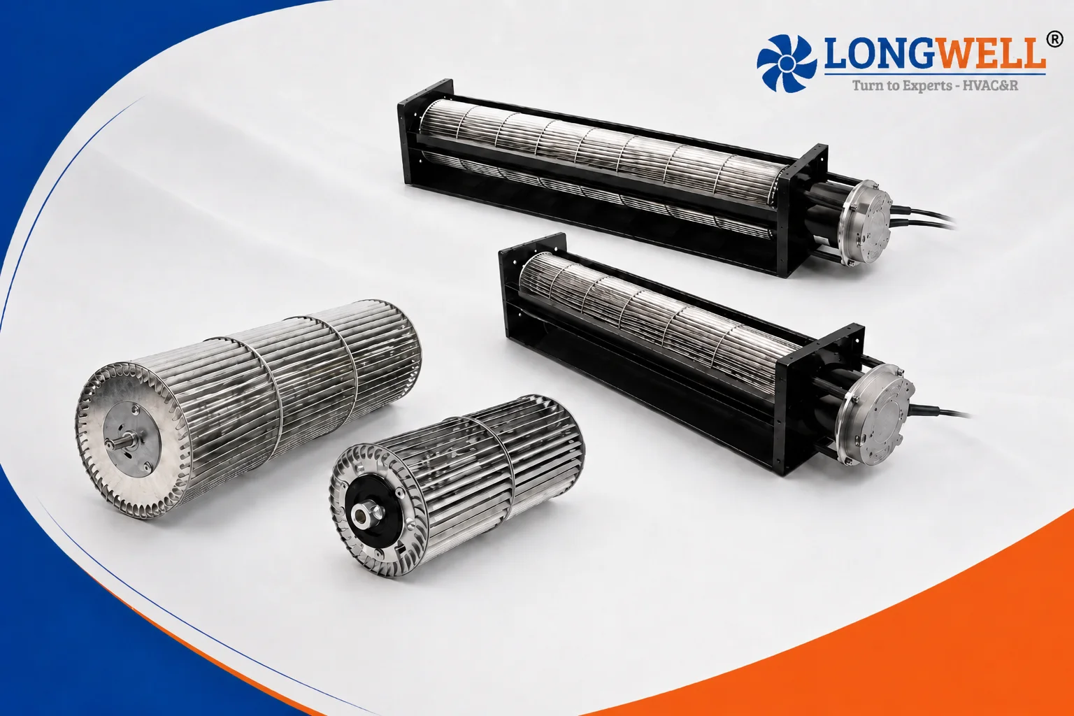
For an axial-family installation example, our tube axial fan installation guide provides additional planning context. Its details should not be transferred to a centrifugal, plenum, roof, cross-flow, or inline fan without the exact product instructions.
Commission the installed operating point
After installation, verify the complete system with guards and panels restored. Confirm rotation, speed, airflow, pressure, motor current or power, vibration, sound, component pressure drops, and the required operating modes. Compare the findings with the selected point and the allowable range for the exact fan and motor.
Measurement location matters. A station immediately after an elbow, damper, transition, or fan discharge may contain swirl and nonuniform velocity. Use the applicable method’s location and traverse requirements, or document an approved alternative and its uncertainty. One reading in disturbed flow cannot prove that the fan meets its rated curve.
Send both ends of the fan for engineering review
A useful review package includes the fan model and arrangement, performance curve, installation drawing, inlet and outlet plan views, nearby fittings and components, available dimensions, support details, access zones, and the intended measurement locations. Include the duty point and operating range rather than only a maximum-airflow value.
The right fan installation clearance is therefore a verified layout, not a universal 3D, 5D, or 10D rule. Model-specific guidance, coordinated access, and measured system performance decide whether the installation is truly done right.