Defining the Tight Duct Constraints
The customer needed an ec mixed flow fan for a tight duct system. First, the ec mixed flow fan had to move 150 m3/h of air. Also, it had to push this airflow against a 100 Pa static pressure drop. Next, the ec mixed flow fan had to fit perfectly inside an existing 125 mm diameter pipe.
Therefore, our spatial limits were absolute. However, the main challenge was the strict noise limit. The customer set very harsh acoustic rules for this project. Specifically, inlet sound power had to stay under 56 dB(A).
Meanwhile, outlet sound power could not exceed 63 dB(A). Finally, the casing radiated noise had to remain below 43 dB(A). Thus, we needed a fan that did not vibrate against the duct walls. Power supply needs added another layer of difficulty.
The original request asked for a basic 230V motor. Instead, the final global design demanded a wide 110-240 VAC range. This wide range ensures the ec mixed flow fan works perfectly in different countries. Furthermore, the customer required PWM speed control and a tachometer output.
This allows smooth adjustments to the ec mixed flow fan speed based on live conditions. Safety and climate rules provided the last set of hurdles. For example, the ec mixed flow fan had to meet strict EN 60335-1 household safety rules. Consequently, it required formal testing to the UL 507 standard for North America.
Ultimately, it needed to operate reliably from -10 to 60 degrees Celsius. Because of this, extreme heat or winter cold could not cause a failure.
Engineering the ec mixed flow fan
Initially, we tested a backward-curved centrifugal fan. A centrifugal wheel easily hits the 100 Pa pressure goal. However, it pushes air out at a sharp radial angle. Consequently, this fast air hits the straight walls of the 125 mm duct.
As a result, the air creates heavy turbulence inside the tube. Therefore, the casing noise jumped much higher than the 43 dB(A) limit. Instead of fixing this with thick acoustic foam, we rejected the centrifugal option entirely. Next, we looked at a basic axial fan.
An axial blade moves a large volume of air in an open space. Even so, it fails rapidly under heavy duct resistance. At 100 Pa of back pressure, a standard 125 mm axial fan stalls out completely. Because of this, the airflow drops well below the 150 m3/h target.
Furthermore, a stalled blade makes a loud, low-frequency hum. Thus, we needed a completely different aerodynamic shape.
Choosing the Mixed Flow Geometry
Ultimately, we picked a mixed flow impeller. This specific design pairs with special 3D guide vanes located behind the blade. First, the ec mixed flow fan squeezes the incoming air diagonally. So, it builds static pressure just like a centrifugal fan. Yet, it avoids the terrible radial air path.
Meanwhile, the downstream 3D guide vanes catch the exiting air. They force the twisting flow back into a straight line. By doing this, we kept the outlet sound safely below the 63 dB(A) limit. Also, this smooth airflow stopped the plastic housing from vibrating. Thus, we met the 43 dB(A) casing noise rule without adding heavy insulation.
Materials and Manufacturing Trade-offs
Still, this choice carried a material cost. We had to make the complex impeller from ABS plastic with fire retardants. Also, the 3D guide vanes required highly precise injection molds. This added extra tooling time to the project schedule. By contrast, a plain metal axial blade is fast and cheap to stamp. Furthermore, adding the 110-240 VAC power circuit raised the motor drive cost.
Finally, we built the finalized model LWDE3G125-IS-01-00. We used a tough plastic shell made of polypropylene with 20 percent glass fiber. Additionally, we balanced the spinning rotor to the strict G6.3 grade. Because of this, the unit runs smoothly at 3000 RPM. The final fan uses just 35 W of input power. However, it delivers up to 417 m3/h and a maximum static pressure of 275 Pa. So, it easily clears the 100 Pa operating target.
Technical Specifications
| Nominal Voltage | 110~240 VAC |
| Frequency | 50/60 Hz |
| Rated Speed | 3000 RPM |
| Rated Current | Under 0.35 A |
| Input Power | 35 W |
| Maximum Airflow | 417 m3/h (245 CFM) |
| Maximum Static Pressure | 275 Pa |
| Operating Temperature | -10 to 60 degrees Celsius |
| Shell Material | PP+GF20% |
| Impeller Material | ABS+FR |
| Bearing Type | Maintenance-free deep groove ball bearings |
| Duty Cycle | S1 Continuous |
| Life Expectancy | 50,000 Hours (L10 at 25 degrees Celsius) |
| Balancing Grade | G6.3 |
| Certifications | CE, ETL, FCC, RoHS, REACH |
The table lists the absolute maximum limits of the fan. However, the most critical numbers were the wide voltage range and the duty cycle. First, the 110-240 VAC input solves the global deployment problem. Next, the S1 continuous duty rating guarantees non-stop running capabilities. Also, the fan survives 60 degrees Celsius for a full 50,000 hours. Thus, the ball bearings will not fail early in hot attic spaces. Finally, the ETL certification confirms it safely meets North American electrical codes.
Reference: AMCA 210 covers the test method behind these figures.
Technical Documentation
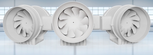
First, this photo shows the white plastic shell, the mounting bracket, and the external speed control box.
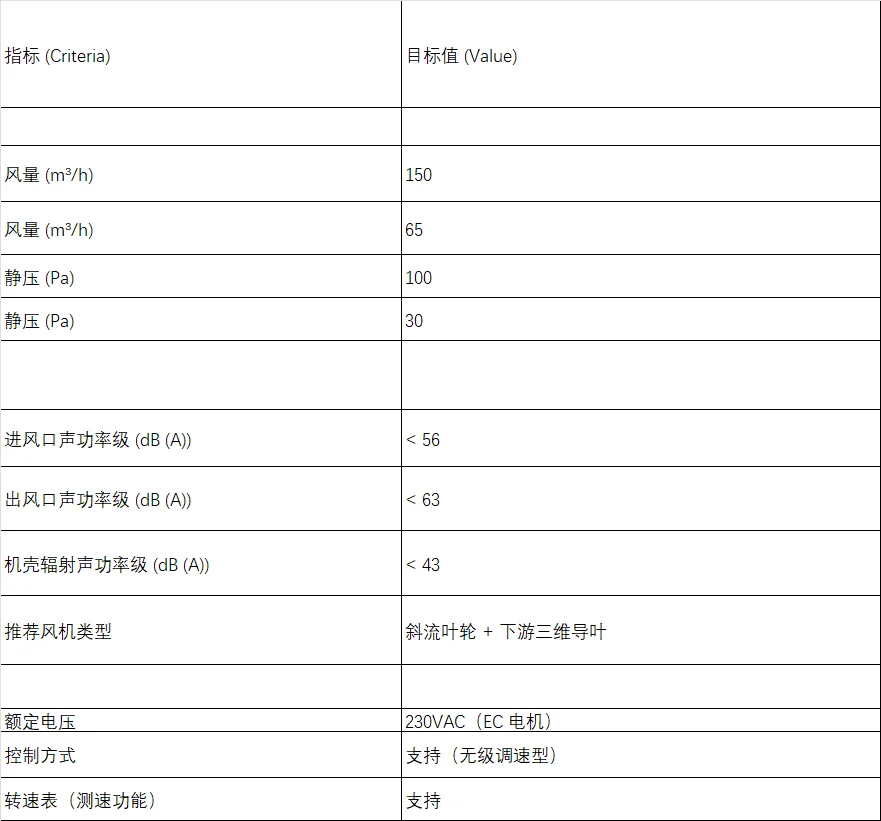
Next, this document outlines the strict acoustic power limits that the customer required us to meet.
Download the full technical specification sheet.
Finally, HVAC engineers use this exact specification sheet to review the aerodynamic curves and dimensional drawings.
Lessons for Your Next Ventilation Project
If you face a similar duct problem, keep these engineering rules in mind.
- First, measure your acoustic limits carefully. Do not simply ask for a quiet fan. Instead, define specific decibel limits for the inlet, the outlet, and the casing radiation. Sound travels very differently through metal ductwork than it does through a plastic shell.
- Next, match your blade shape to the expected pressure drop. If your duct system causes more than 80 Pa of resistance, standard axial fans will fail. Therefore, you must use a mixed flow geometry to push the air forward.
- Finally, tell the factory exactly how you want to control the motor. You should state clearly if you need a PWM signal or an analog voltage dial. Thus, the maker can program the internal motor drive correctly on the very first try.
Related: Duct Fans.
Common Engineering Questions
Technical Documentation & Resources
Browse our duct fans range, the inline duct fans section, or mixed flow fans.
Have a Similar Fan Requirement?
Longwell’s engineering team delivers custom spec sheets and samples within 90 days. Since 1990, we have supplied EC fans and blowers to OEMs across HVAC, cold chain, data center, and industrial applications worldwide.
Browse Related Products:
🏆 ISO 9001 / ISO 14001 / ISO 45001 | CE (TÜV) | UL/ETL | ATEX Zone 21/22 | AMCA 210-16 / ISO 5801 tested