The 615mm Cross Flow Impeller Requirement
The customer contacted us to design a new cross flow impeller. They needed a long rotating part for a wide air distribution unit. First, the unit had to measure exactly 615 mm long. Next, the outer diameter had to be exactly 90.5 mm.
Because this part acts as a wide low-profile evaporator, continuous and quiet airflow was a strict rule. The heavy commercial setting demands reliable cooling performance. The design needed to spin clockwise smoothly. Furthermore, it required a strong built-in bearing.
This bearing turns directly on an 8 mm steel shaft. The physical shape is very long and thin. Consequently, keeping the part stiff was our main challenge. The system motor spins the fan at 1600 RPM.
So, the long rotor must not bend or make strange noises. We had to hold very tight size limits during production. Otherwise, the long fan would hit its outer metal case. First, we kept the maximum radial runout under 0.7 mm.
Next, we kept the axial runout safely under 0.6 mm. Finally, the shaft runout had to stay strictly under 0.2 mm. Managing vibration was also very critical for long-term use. The customer set a strict dynamic balance rule.
Specifically, residual unbalance must stay under 0.3g when spinning at 1200 RPM. Meanwhile, the buyer needed full technical drawings on the same day. Therefore, we had to pick the plastic and weld method quickly. The final approved unit meets rigorous ISO 5801 test rules.
Engineering a Rigid 615mm Span
First, we looked at base plastics for the spinning blades. Standard ABS works well for many short parts. However, a 615 mm span bends heavily under high loads. At 1600 RPM, normal plastic will surely warp out of shape.
Consequently, the moving blades would scrape the metal outer case. Instead, we picked a strong Acrylonitrile Styrene mix. This custom mix has 30 percent glass fiber added. In short, this AS+GF30% material adds immense structural stiffness.
The clear trade-off is a materially higher cost per unit. Also, the total rotor mass gets slightly heavier. Even so, we accepted this extra weight to stop high-speed bending.
Ultrasonic Welding Constraints
Next, we solved how to attach the long blades securely. Simple mechanical snap joints fail quickly in this application. The long horizontal span twists too much when the motor starts. Instead, we chose exact ultrasonic welding for every single joint.
The strict customer rule allowed no false or leaky welds. Therefore, the strong sound waves melt the plastic perfectly. This creates a strong and permanent bond across the whole length. As a result, the outer leaves stay entirely smooth.
By contrast, messy manual joints would cause loud wind noise. Smooth blades are absolutely vital to keep the unit quiet.
Managing High-Speed Unbalance
Finally, we had to balance this long cross flow impeller accurately. A long fan needs very stable metal anchors. First, we added a solid 8 mm steel shaft. This strong steel shaft is exactly 60 mm long.
Next, it features a precisely cut 15 mm flat side. A small M4X6.5 screw locks the metal shaft tight. We had to keep unbalance strictly under 0.3g at 1200 RPM. However, the approved design could only use three metal balance clips.
Using more clips usually means the plastic mold is bad. So, the stiff glass plastic saved the entire project. It helped us meet the strict sound targets without extra metal weights. The fully approved model is LWPI-φ90.5×615-06.
Cross Flow Impeller Technical Specs
| Parameter | Specification |
|---|---|
| Model Number | LWPI-φ90.5×615-06 |
| Impeller Diameter | 90.5 mm |
| Impeller Length | 615 ± 2 mm |
| Material | AS + GF30% |
| Color | Black |
| Bearing Type | Built-in |
| Bushing Diameter | 8 mm |
| Steel Shaft Diameter | 8 mm (+0.022 / -0) |
| Steel Shaft Length | 60 mm |
| Steel Shaft Cross-Section | 15 mm |
| Rotation | Clockwise (CW) |
| Max Radial Runout | < 0.7 mm |
| Max Axial Runout | < 0.6 mm |
| Max Shaft Runout | < 0.2 mm |
| Operating Speed (Acoustic Limit) | 1600 RPM |
| Residual Unbalance (at 1200 RPM) | ≤ 0.3g |
| Balancing Clips Limit | ≤ 3 pcs |
| Fastener Spec | Screw M4X6.5 |
The tight runout limits are the most important numbers above. First, keeping the radial runout under 0.7 mm is highly vital. It strictly stops the 615 mm fan from hitting the outer wall. Furthermore, the 0.3g unbalance limit directly protects the fan motor. Consequently, the built-in bearings will easily last much longer.
Reference: ISO 21940 covers the test method behind these figures.
Technical Documentation
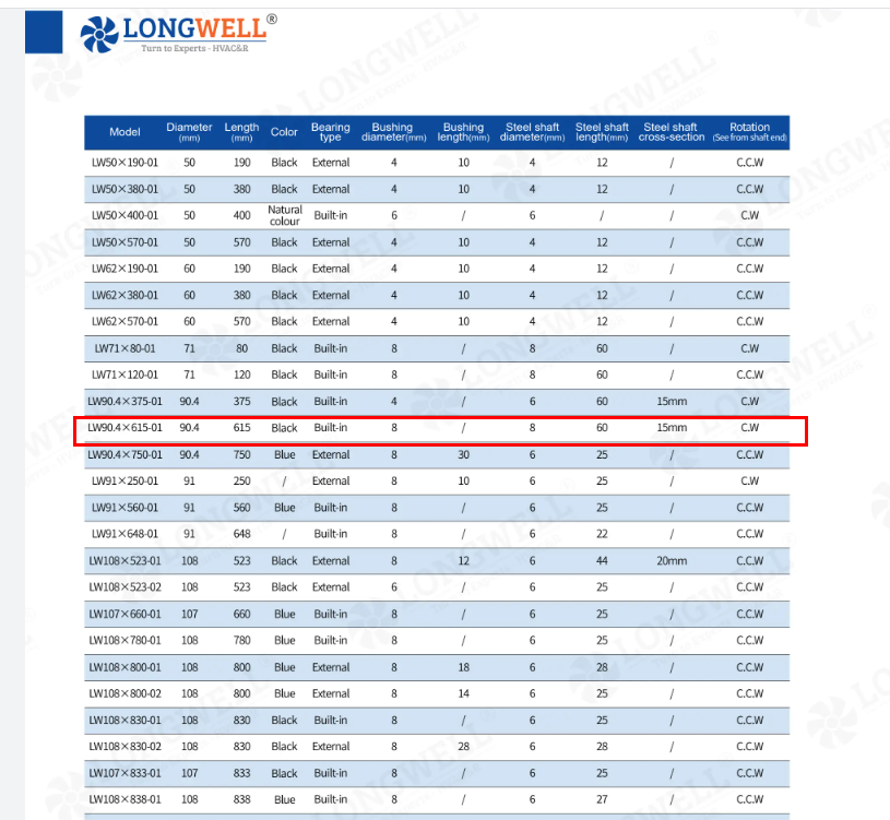
Cross Flow Selection Specs (PDF)
First, this document shows standard lengths and bearing types. Engineers need it to check exact shaft sizes.
Cross Flow Order Table (XLS)
Next, this technical sheet lists the raw material data. Procurement teams use it to cross-check cross flow impeller models.
Finally, this manufacturing drawing shows all exact runout limits. It guides the precise final ultrasonic welding steps.
Specifying Long HVAC Rotors
Standard plastics often fail when you specify a cross flow impeller. Therefore, follow these simple engineering rules for long and thin shapes:
- First, measure your true radial runout limit carefully. Long plastic parts naturally sag in the middle under heavy gravity. So, you must demand a strict runout limit cleanly under 1.0 mm.
- Next, carefully balance the part stiffness against its total physical weight. Specify stiff glass plastics like AS+GF30% for any part length extending over 500 mm.
- Furthermore, do not ignore the real dynamic balancing speed. Always require actual dynamic balance tests at your exact target RPM.
- Finally, share your exact metal shaft sizes very early in the process. This helps the tool factory cut the built-in bearing correctly on the very first try.
We build our precise plastic molds directly inside our Ningbo plant. Consequently, our factory engineers adjust these tight runout limits very fast.
Related: Cross Flow Fans.
Technical Documentation & Resources
Browse our axial fans range, the AC axial fans section, or EC axial fans.
Have a Similar Fan Requirement?
Longwell’s engineering team delivers custom spec sheets and samples within 90 days. Since 1990, we have supplied EC fans and blowers to OEMs across HVAC, cold chain, data center, and industrial applications worldwide.
Browse Related Products:
🏆 ISO 9001 / ISO 14001 / ISO 45001 | CE (TÜV) | UL/ETL | ATEX Zone 21/22 | AMCA 210-16 / ISO 5801 tested