Description
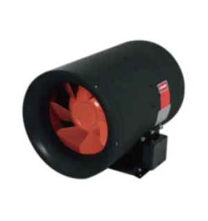
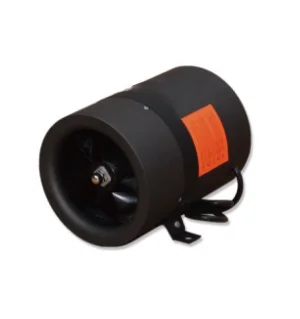
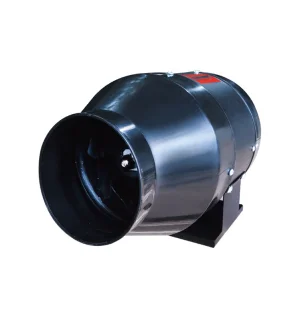
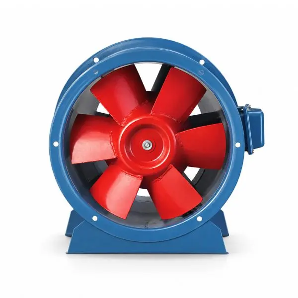
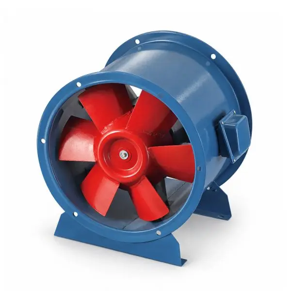
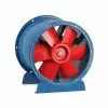
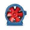
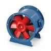
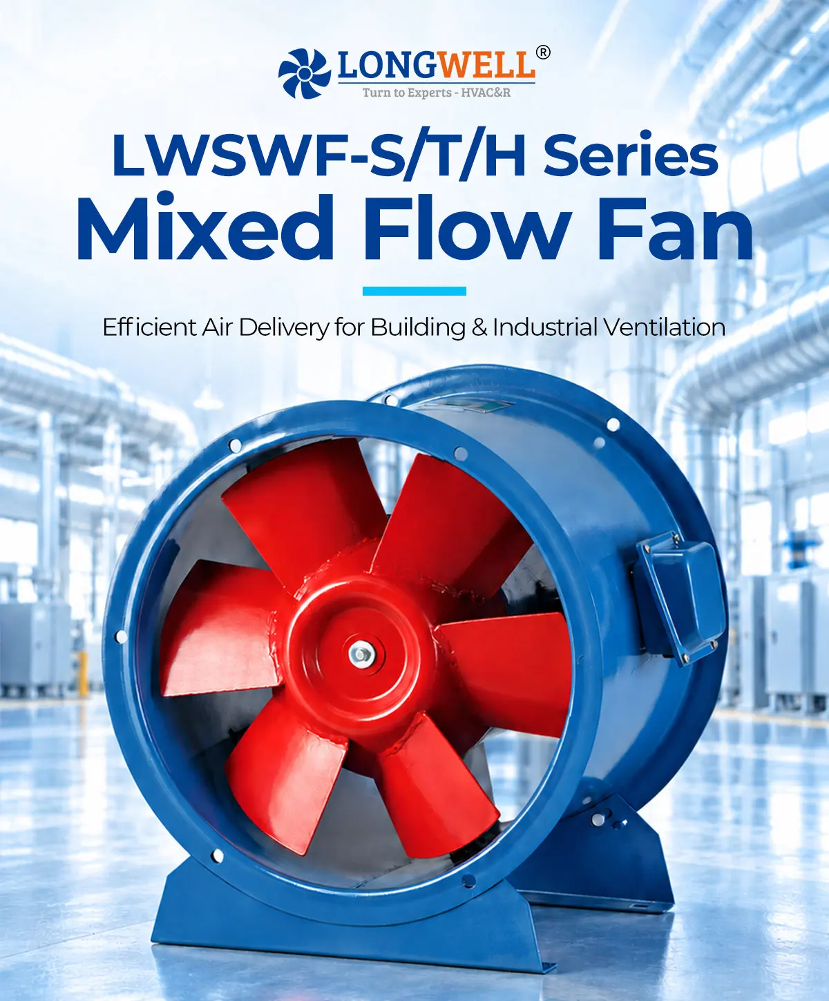
Mixed Flow Fan
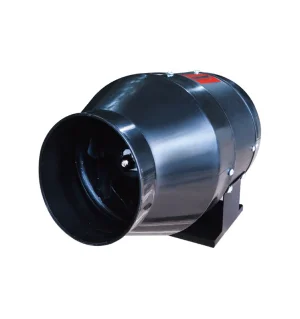
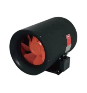
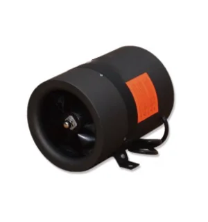
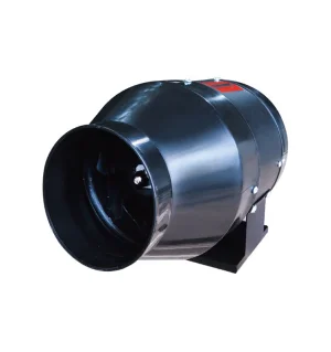
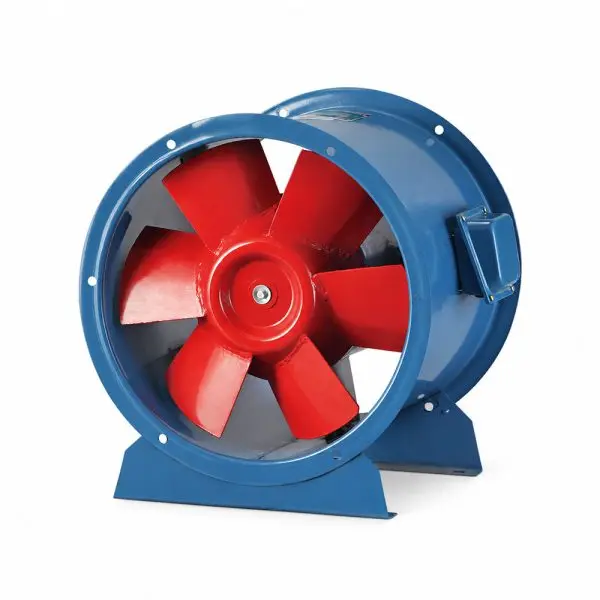
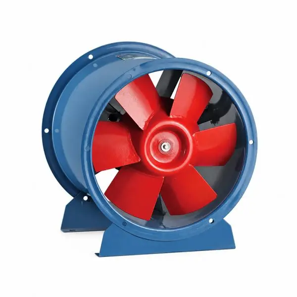
Efficient Air Delivery for Building & Industrial Ventilation. Integrates axial volume with centrifugal pressure characteristics.
Core Design Features
Optimized for low-noise, high-efficiency inline duct ventilation across commercial and industrial zones.
Design
Ventilation
Range
Connection
Mounting Feet
Applications
Product Specifications
Complete performance parameters and dimensional data for the LWSWF-S, T, and H series.
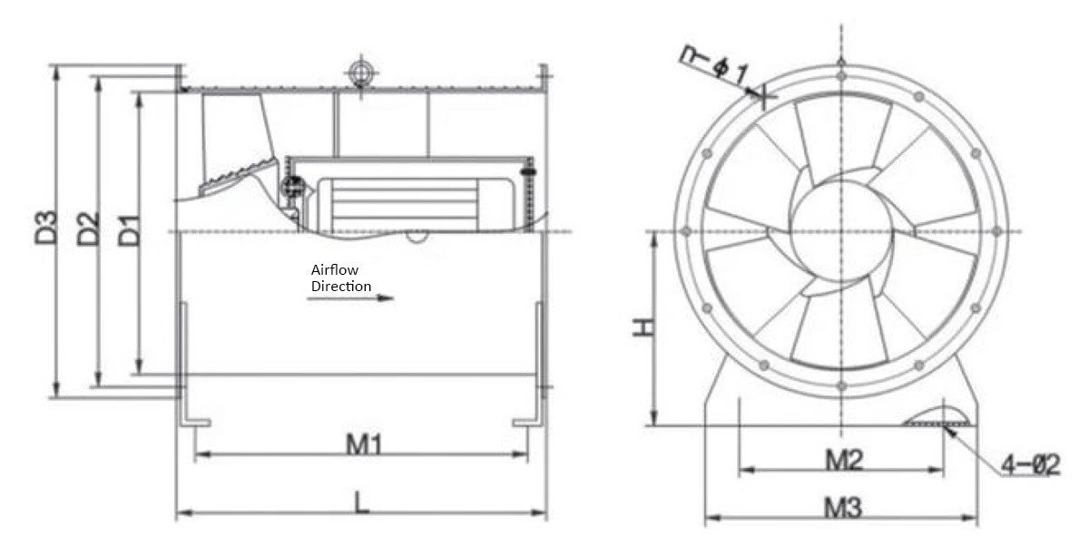
| Model | D1 | D2 | D3 | Type I L | Type I M1 | Type II L | Type II M1 | Type III L | Type III M1 | M2 | M3 | H | nXΦ1 | Φ2 |
|---|---|---|---|---|---|---|---|---|---|---|---|---|---|---|
| LWSWF-S/T/H-2.5A | 260 | 290 | 320 | 300 | 265 | / | / | / | / | 170 | 220 | 190 | 6×Φ8 | Φ12 |
| LWSWF-S/T/H-3A | 310 | 340 | 360 | 300 | 265 | / | / | 420 | 385 | 230 | 280 | 210 | 8×Φ8 | Φ12 |
| LWSWF-S/T/H-4A | 410 | 440 | 470 | 380 | 340 | / | / | 500 | 460 | 310 | 370 | 280 | 6×Φ10 | Φ14 |
| LWSWF-S/T/H-4.5A | 460 | 490 | 520 | 400 | 366 | 610 | 575 | 610 | 575 | 300 | 380 | 300 | 8×Φ11 | Φ14 |
| LWSWF-S/T/H-5A | 510 | 540 | 570 | 440 | 405 | 590 | 555 | 590 | 555 | 340 | 420 | 325 | 8×Φ11 | Φ14 |
| LWSWF-S/T/H-6A | 610 | 640 | 670 | 490 | 436 | 640 | 605 | 590 | 555 | 430 | 510 | 385 | 10×Φ11 | Φ14 |
| LWSWF-S/T/H-7A | 710 | 745 | 780 | 550 | 495 | 600 | 545 | 720 | 665 | 500 | 600 | 440 | 12×Φ12 | Φ14 |
| LWSWF-S/T/H-8A | 810 | 852 | 890 | 740 | 685 | 830 | 775 | 830 | 775 | 560 | 660 | 500 | 12×Φ12 | Φ18 |
| LWSWF-S/T/H-9A | 910 | 942 | 980 | 740 | 685 | 890 | 834 | 840 | 784 | 700 | 800 | 560 | 12×Φ12 | Φ18 |
| LWSWF-S/T/H-10A | 1000 | 1042 | 1080 | 780 | 724 | 950 | 894 | 840 | 784 | 750 | 850 | 640 | 12×Φ12 | Φ18 |
| LWSWF-S/T/H-11A | 1100 | 1142 | 1180 | 810 | 734 | 950 | 875 | 880 | 805 | 800 | 1000 | 680 | 14×Φ12 | Φ18 |
| LWSWF-S/T/H-12A | 1210 | 1256 | 1290 | 1050 | 984 | 1050 | 984 | 1050 | 984 | 1000 | 1100 | 700 | 14×Φ12 | Φ18 |
| LWSWF-S/T/H-13A | 1310 | 1350 | 1390 | 1080 | 1014 | 1200 | 1130 | 1130 | 1064 | 1100 | 1200 | 750 | 16×Φ13 | Φ18 |
| Model | Speed (r/min) | Matching Motor (kW) | Air Volume (m³/h) | Total Pressure (Pa) | Noise [dB(A)] |
|---|---|---|---|---|---|
| LWSWF-S-2.5A-0.18-4P-1-001 | 1450 | 0.18 | 1362-743 | 96-166 | ≤64 |
| LWSWF-S-3A-0.25-4P-1-001 | 1450 | 0.25 | 2312-1606 | 121-236 | ≤66 |
| LWSWF-S-4A-0.37-4P-1-001 | 1450 | 0.37 | 4512-2765 | 128-285 | ≤71 |
| LWSWF-S-4.5A-0.55-4P-1-001 | 1450 | 0.55 | 4728-3160 | 182-306 | ≤73 |
| LWSWF-S-5A-1.1-4P-1-001 | 1450 | 1.1 | 8652-4896 | 196-382 | ≤77 |
| LWSWF-S-6A-1.5-4P-1-001 | 1450 | 1.5 | 11625-7560 | 165-382 | ≤79 |
| LWSWF-S-7A-3-4P-1-001 | 1450 | 3 | 18800-11780 | 329-470 | ≤82 |
| LWSWF-S-7A-1.1-6P-1-002 | 960 | 1.1 | 13820-8246 | 186-278 | ≤74 |
| LWSWF-S-8A-4-6P-1-001 | 960 | 4 | 25467-16269 | 193-516 | ≤82 |
| LWSWF-S-9A-5.5-6P-1-001 | 960 | 5.5 | 34206-22011 | 282-564 | ≤86 |
| LWSWF-S-10A-7.5-6P-1-001 | 960 | 7.5 | 44054-29902 | 288-496 | ≤86 |
| LWSWF-S-11A-11-6P-1-001 | 960 | 11 | 48729-35294 | 310-516 | ≤86 |
| LWSWF-S-12A-15-8P-1-001 | 720 | 15 | 64292-47534 | 429-625 | ≤91 |
| LWSWF-S-13A-15-8P-1-001 | 720 | 15 | 71565-51596 | 441-637 | ≤91 |
| Model | Speed (r/min) | Two-speed Motor (kW) | Air Volume (m³/h) | Total Pressure (Pa) | Noise [dB(A)] |
|---|---|---|---|---|---|
| LWSWF-T-5A-5.5-2P-1-001 | 2900 | 5.5 | 13110-9876 | 801-1316 | ≤83 |
| LWSWF-T-5A-4.5-4P-1-002 | 1450 | 4.5 | 8652-4896 | 196-382 | ≤77 |
| LWSWF-T-6A-8-2P-1-001 | 2900 | 8 | 19230-15210 | 836-1365 | ≤85 |
| LWSWF-T-6A-8.5-4P-1-002 | 1450 | 6.5 | 11625-7560 | 165-382 | ≤79 |
| LWSWF-T-7A-2.8-4P-1-001 | 1450 | 2.8 | 18800-11780 | 329-470 | ≤82 |
| LWSWF-T-7A-2.2-6P-1-002 | 960 | 2.2 | 13820-8246 | 186-278 | ≤74 |
| LWSWF-T-8A-11-4P-1-001 | 1450 | 11 | 37350-28564 | 809-1305 | ≤90 |
| LWSWF-T-8A-9-6P-1-002 | 960 | 9 | 25467-16269 | 193-516 | ≤82 |
| LWSWF-T-9A-17-4P-1-001 | 1450 | 17 | 46138-33579 | 785-1343 | ≤92 |
| LWSWF-T-9A-8-6P-1-002 | 960 | 8 | 34206-22011 | 282-564 | ≤86 |
| LWSWF-T-10A-24-4P-1-001 | 1450 | 24 | 51821-40528 | 792-1378 | ≤93 |
| LWSWF-T-10A-8-6P-1-002 | 960 | 8 | 44054-29902 | 288-496 | ≤86 |
| LWSWF-T-11A-24-4P-1-001 | 1450 | 24 | 59521-48177 | 806-1382 | ≤94 |
| LWSWF-T-11A-8-6P-1-002 | 960 | 8 | 48729-35294 | 310-516 | ≤86 |
| LWSWF-T-12A-25-6P-1-001 | 960 | 25 | 71092-55852 | 786-1308 | ≤95 |
| LWSWF-T-12A-12-8P-1-002 | 720 | 12 | 64292-47534 | 429-625 | ≤91 |
| LWSWF-T-13A-30-6P-1-001 | 960 | 30 | 87761-68652 | 805-1329 | ≤95 |
| LWSWF-T-13A-18-8P-1-002 | 720 | 18 | 71565-51596 | 441-637 | ≤91 |
| Model | Power (kW-p) | Speed (r/min) | Air Volume (m³/h) | Total Pressure (Pa) | Noise [dB(A)] |
|---|---|---|---|---|---|
| LWSWF-H-3A-2.2-2P-1-001 | 2.2 | 2900 | 4652-3212 | 512-883 | 73 |
| LWSWF-H-4A-4-2P-1-001 | 4.0 | 2900 | 7228-5242 | 654-1248 | 78 |
| LWSWF-H-4.5A-5.5-2P-1-001 | 5.5 | 2900 | 9169-7124 | 672-1298 | 80 |
| LWSWF-H-5A-5.5P-1-001 | 5.5 | 2900 | 13110-9876 | 801-1316 | 83 |
| LWSWF-H-6A-7.5-2P-1-001 | 7.5 | 2900 | 19230-15210 | 836-1365 | 85 |
| LWSWF-H-7A-11-4P-1-001 | 11 | 1450 | 31380-27330 | 600-980 | 92 |
| LWSWF-H-8A-15-4P-1-001 | 15 | 1450 | 37350-28564 | 809-1305 | 91 |
| LWSWF-H-9A-18.5-4P-1-001 | 18.5 | 1450 | 46138-33579 | 785-1343 | 92 |
| LWSWF-H-10A-18.5-4P-1-001 | 18.5 | 1450 | 51821-40528 | 792-1378 | 93 |
| LWSWF-H-11A-22-4P-1-001 | 22 | 1450 | 59521-48177 | 806-1382 | 94 |
| LWSWF-H-12A-22-6P-1-001 | 22 | 960 | 71092-55852 | 786-1308 | 95 |
| LWSWF-H-13A-30-6P-1-001 | 30 | 960 | 87761-68652 | 805-1329 | 95 |
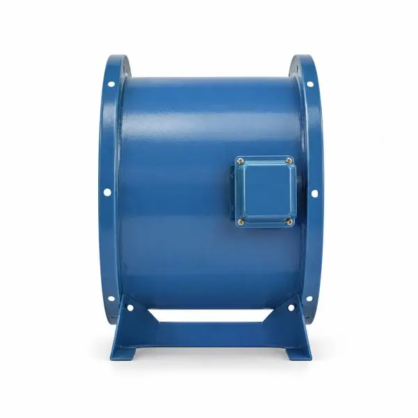
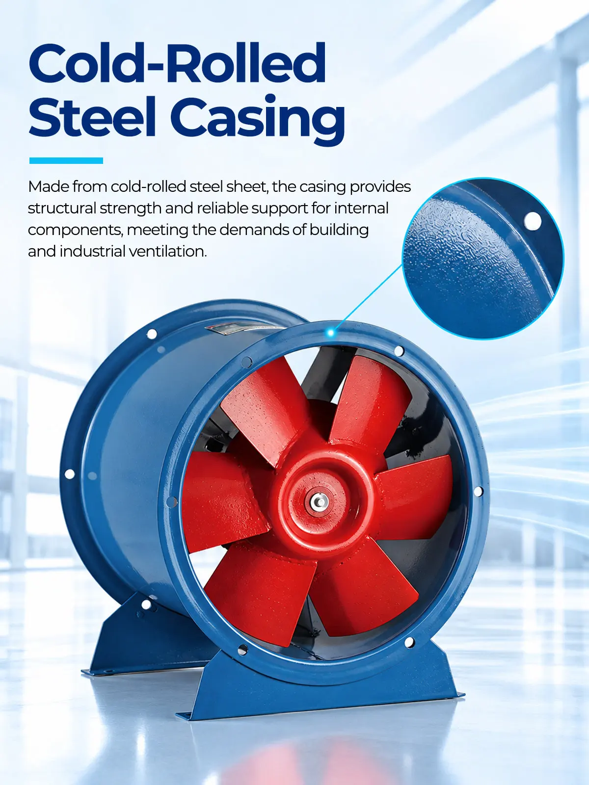
Cold-Rolled Steel Casing
The casing is constructed from high-quality cold-rolled steel, providing strong structural rigidity and reliable mechanical protection.
Inline duct fans are often subjected to external mechanical stress and internal aerodynamic pressure. We utilize precision cold-rolled steel to form a highly rigid tubular housing. A specialized industrial protective coating defends the exterior against humidity and corrosive elements commonly found in building ventilation networks.
- Structural Rigidity — thick-gauge steel resists mechanical drumming and flex
- Protective Coating — shields the metal from humid factory atmospheres
- Inline Support — robust enough to bear the weight of connected ducting sections
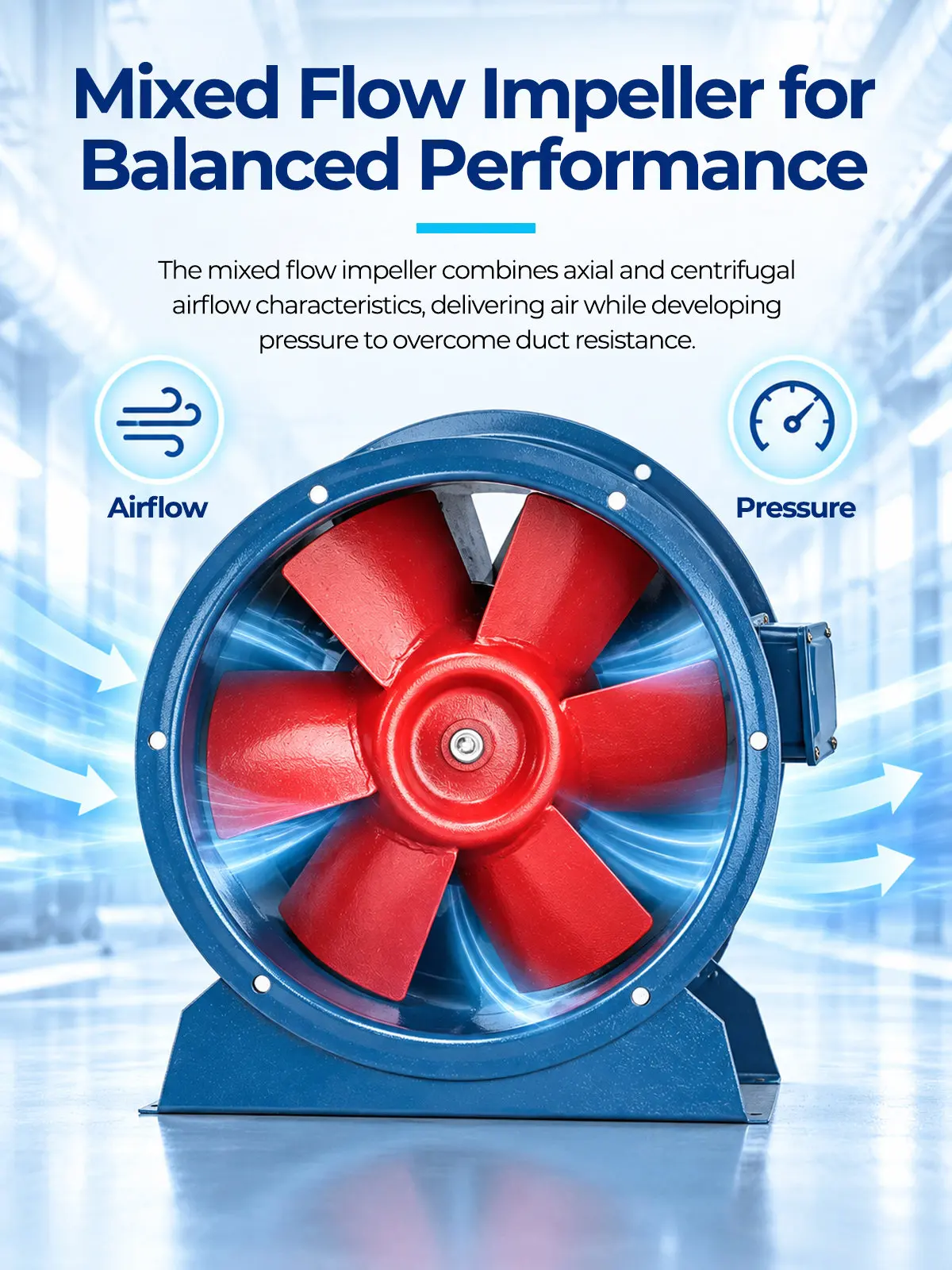
Mixed Flow Impeller
The mixed-flow blade design combines the airflow volume advantages of an axial fan with the stable static pressure characteristics of a centrifugal fan.
This specialized hybrid geometry accelerates air efficiently along the rotation axis while imparting radial velocity to overcome duct resistance. Dynamically balanced to tight industrial tolerances, it prevents eccentric stalling and supports smooth, high-capacity air delivery.
- Hybrid Aerodynamics — delivers high throughput against moderate-to-high resistance
- Vibration Reduction — precise balancing eliminates damaging rotational stress
- Optimized Blade Profile — maximizes kinetic energy transfer to the airstream
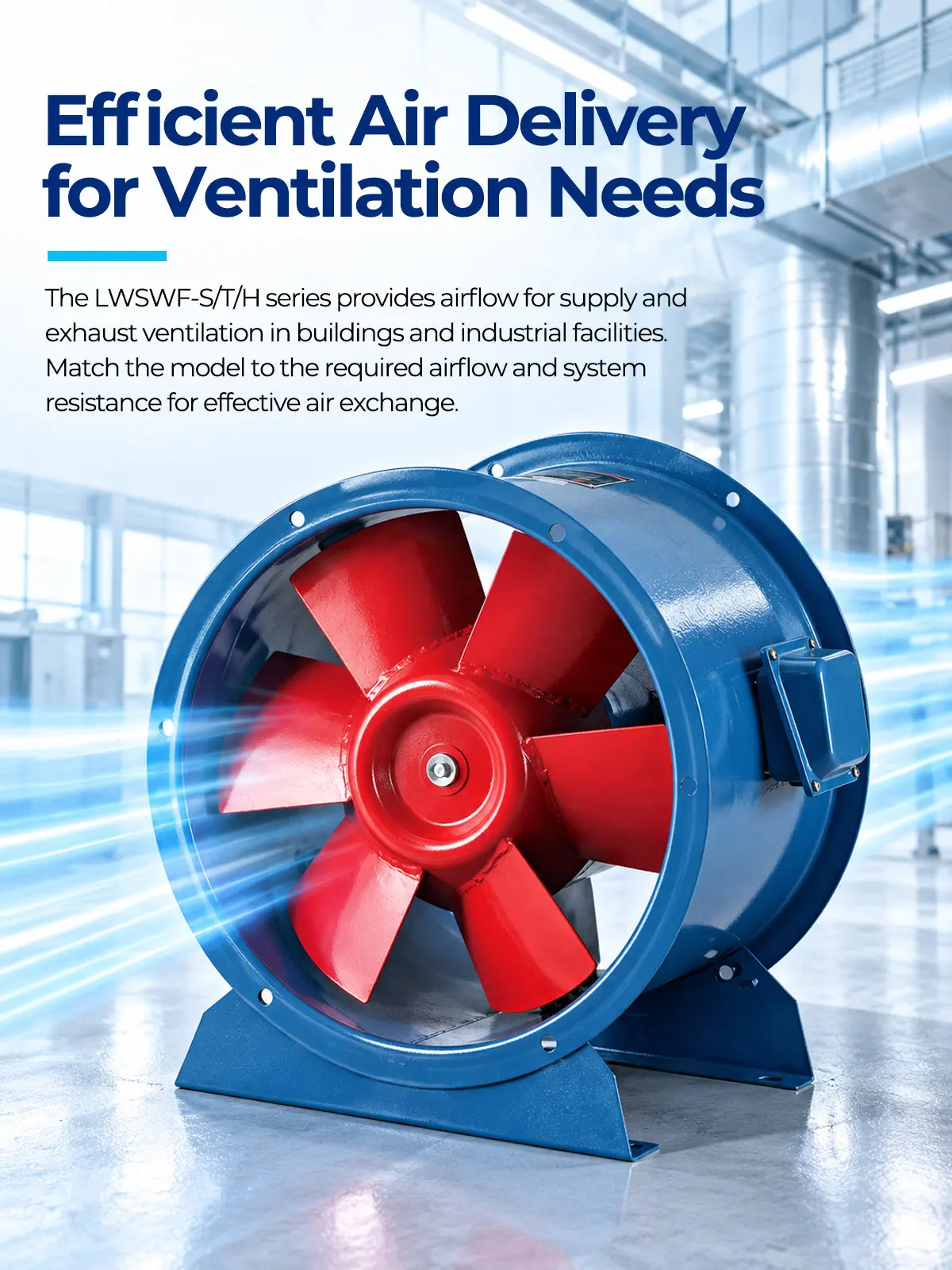
Efficient Air Delivery
The streamlined casing and impeller profile help reduce aerodynamic drag, supporting steady and highly efficient volumetric throughput.
Airflow pulsation and turbulence waste electrical energy and generate noise. The LWSWF series smooths the internal air path, ensuring a perfectly linear discharge through the tubular housing. This stable delivery keeps ventilation rates consistent across expansive commercial buildings.
- Streamlined Air Path — minimizes internal collisions and energy loss
- Pulsation-Free Delivery — ensures constant forced draft for building HVAC
- High Volumetric Throughput — moves up to 87,761 m³/h effortlessly
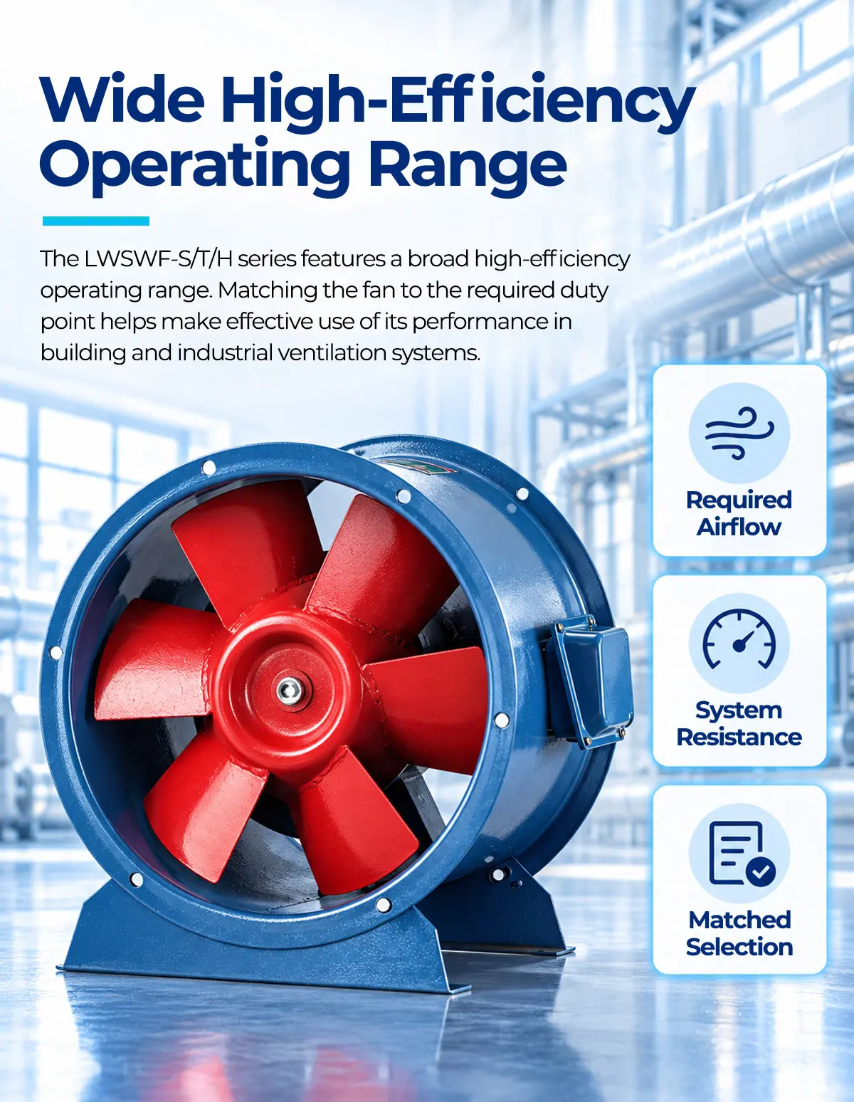
Wide High-Efficiency Operating Range
Unlike standard fans, the mixed-flow aerodynamic curve remains highly efficient across a broader spectrum of static pressures.
Industrial HVAC systems frequently experience fluctuating duct resistance due to filter loading or damper adjustments. The LWSWF series features a forgiving performance curve, allowing the fan to operate stably without surging or stalling, even when the system pressure varies significantly.
- Broad Performance Curve — maintains efficiency under changing backpressures
- Anti-Stall Characteristics — resists aerodynamic surging in complex duct layouts
- Energy Conservation — reduces overall electrical consumption for facility managers
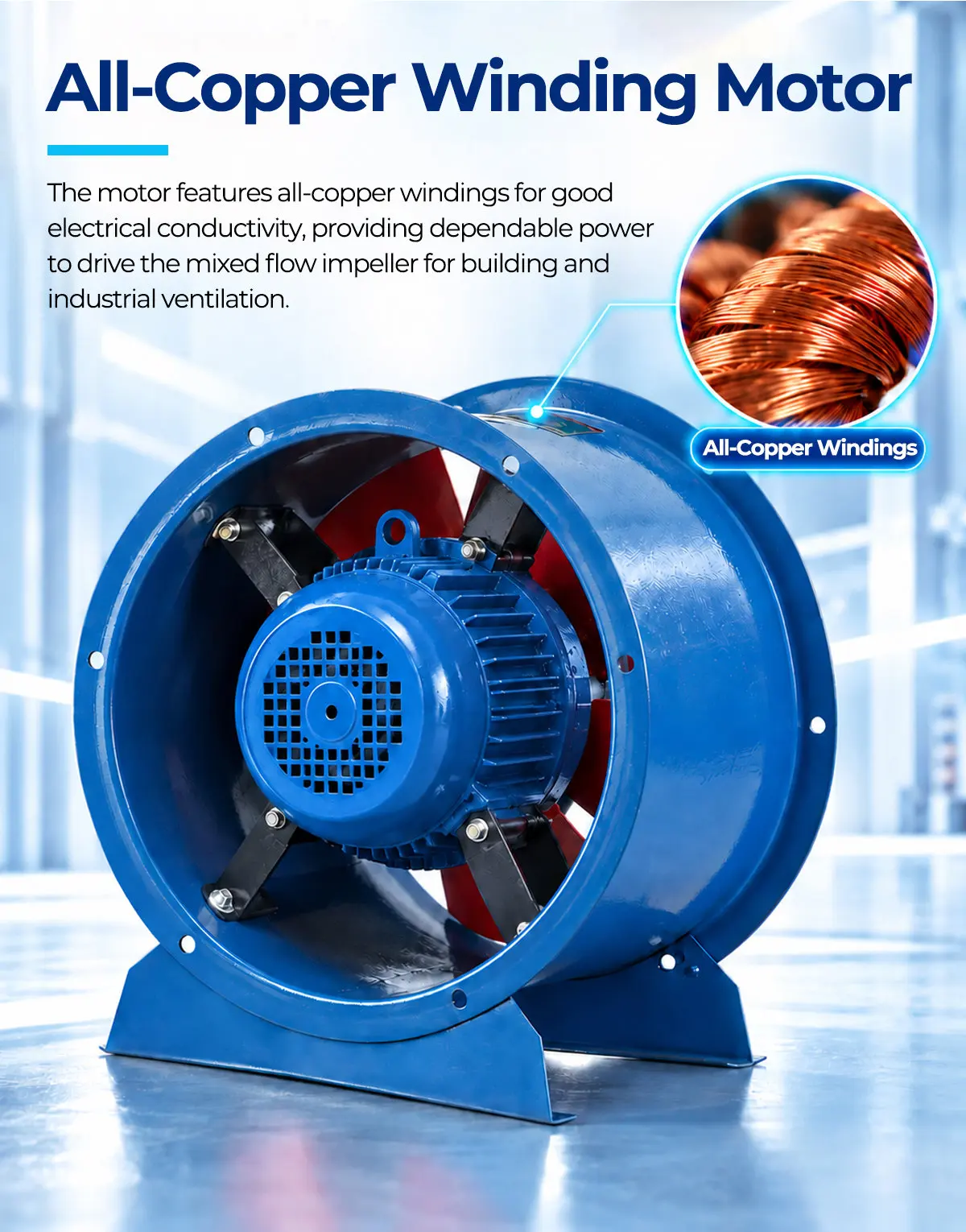
All-Copper Winding Motor
Equipped with an all-copper winding motor rated for continuous S1 industrial duty, providing reliable torque to handle the specific aerodynamic load of the mixed flow wheel.
Large-scale building ventilation demands 24/7 operation. By utilizing pure copper stators, these direct-drive motors offer superior thermal conductivity. This limits heat accumulation inside the inline casing, keeping the powertrain operating reliably shift after shift.
- S1 Continuous Duty — built for non-stop commercial and industrial processing
- Pure Copper Windings — maximizes electrical efficiency and heat dissipation
- Matched Torque — eliminates startup stalling against heavy air columns
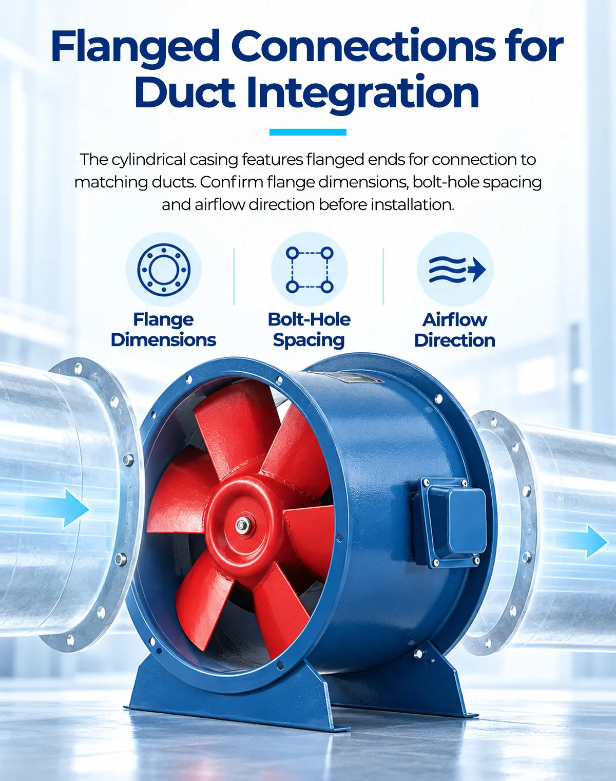
Flanged Connections for Duct Integration
Both the inlet and outlet feature standard flanged rings, allowing mechanical contractors to bolt the unit directly into existing circular ductwork.
The inline tubular design is engineered to minimize installation footprint. The pre-drilled flanges provide a secure, airtight seal against mating pipes, streamlining the mechanical integration process and lowering on-site fabrication costs.
- Standard Flanges — mates easily with commercial circular ducting
- Airtight Seal — prevents pressure bleed-off in high-resistance networks
- Inline Footprint — saves valuable lateral space in cramped utility rooms
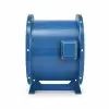
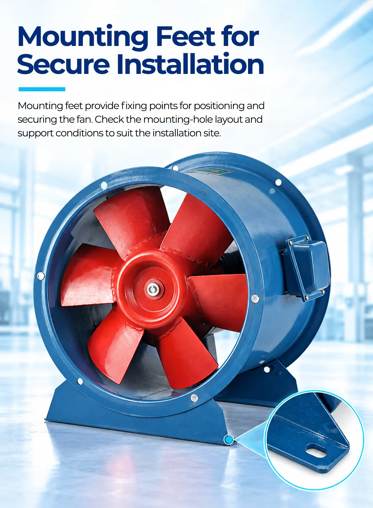
Mounting Feet for Secure Installation
The heavy-duty mounting bracket provides a rigid anchor point, securing the fan to structural channels or concrete pads.
High-capacity mixed flow fans generate significant rotational torque. The factory-welded steel mounting feet distribute this mechanical load efficiently. Bolting the unit down helps isolate operational vibration from the connected pipework, protecting building infrastructure.
- Rigid Anchor Point — prevents the unit from shifting under heavy aerodynamic load
- Vibration Isolation — protects thin-walled ducting from sympathetic shaking
- Pre-drilled Holes — allows for rapid integration into OEM machinery and plant floors
Versatile Applications in Building & Industry
Inline design streamlines ductwork in expansive commercial facilities and factory spaces.

Office Buildings
Provides low-noise, high-volume air exchange through extensive centralized HVAC duct networks.

Hotels
Maintains stable static pressure across long corridors to ensure consistent fresh air delivery to all rooms.

Commercial & Public Buildings
Integrates compactly into utility ceilings, moving massive air volumes without occupying floor space.
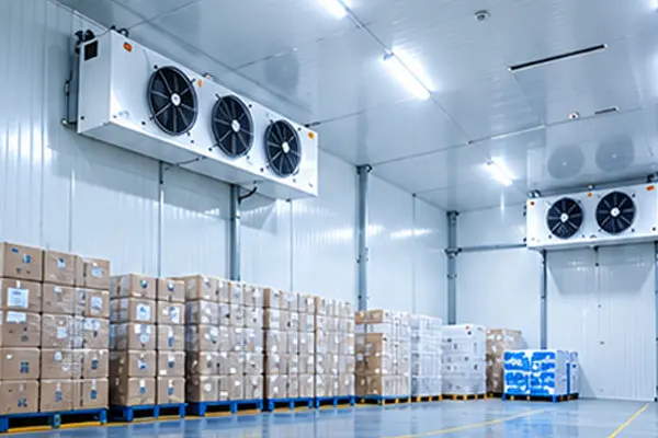
Cold Storage Facilities
Circulates chilled air rapidly to maintain uniform ambient temperatures in large warehousing environments.
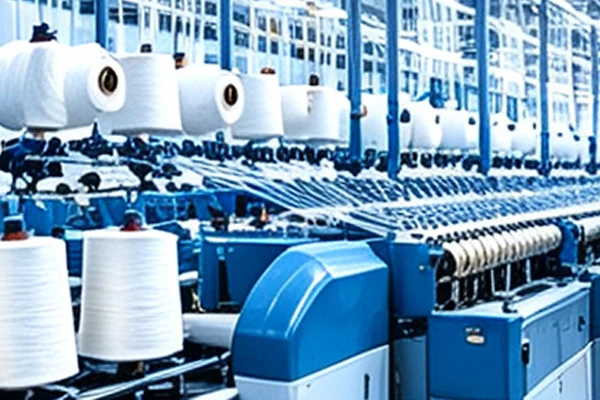
Textile Equipment
Drives forced air through production machinery to manage localized humidity and fiber dust control.
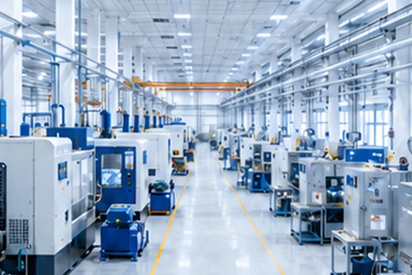
Factory Workshops
Provides powerful inline exhaust to clear heat and stale air across large manufacturing floors.
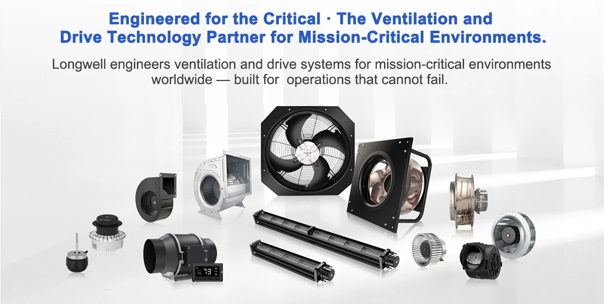
LONGWELL — Trusted Industrial Fan Manufacturer Since 1990
Founded in 1990 in Yuyao, Ningbo — the heart of China’s advanced manufacturing belt — LONGWELL has grown from a precision fan component workshop into a vertically integrated ventilation technology group. Today we engineer AC, DC and EC fan and motor systems with 4,000 m²+ of manufacturing floor, dedicated aerodynamics and CFD simulation labs, and a global export network spanning Europe, the Americas and Asia-Pacific.
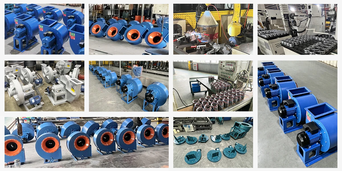
From material selection to final balancing, every LONGWELL fan is built on automated lines, computer-balanced impellers and 100% run-test before shipment. We are certified to ISO 9001:2015 and ISO 14001, with CE, UL/ETL, RoHS and EAC compliance, and performance tested to the AMCA 210/211 method.
Production & Delivery
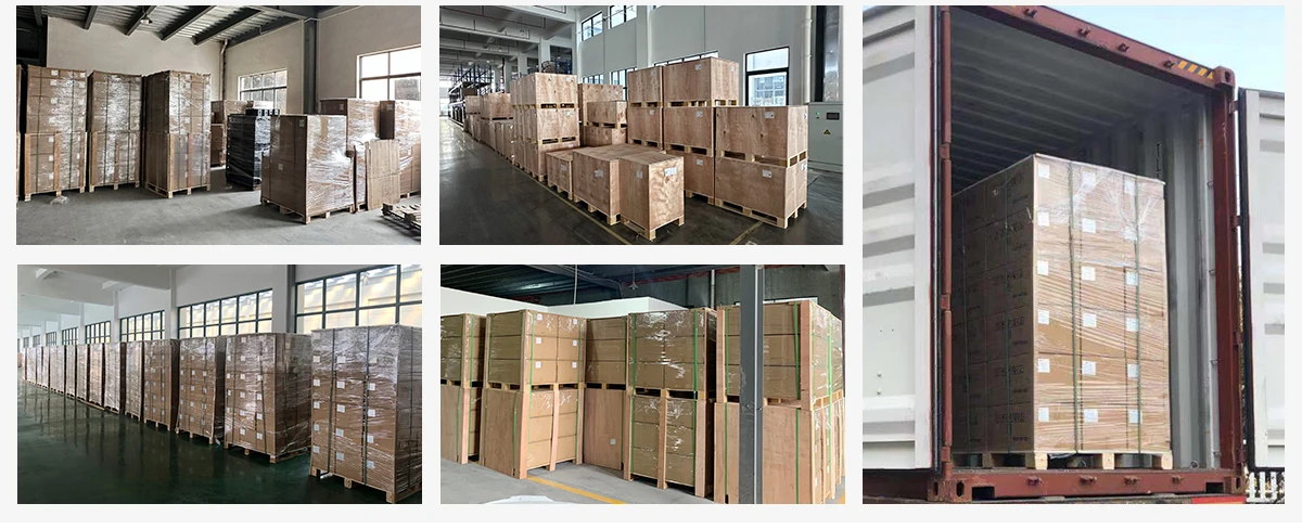
Automated lines, computer-balanced impellers and a 100% run-test on every unit, so each LWSWF fan arrives ready to install.
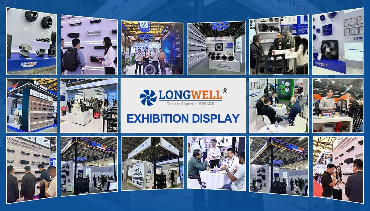
Global HVAC&R Exhibitions Participation
Meeting HVAC distributors, project contractors, and OEM engineering teams at international trade fairs worldwide.
Trusted by Leading Global Brands
24+ commercial equipment builders rely on LONGWELL for industrial fans and blowers every year.
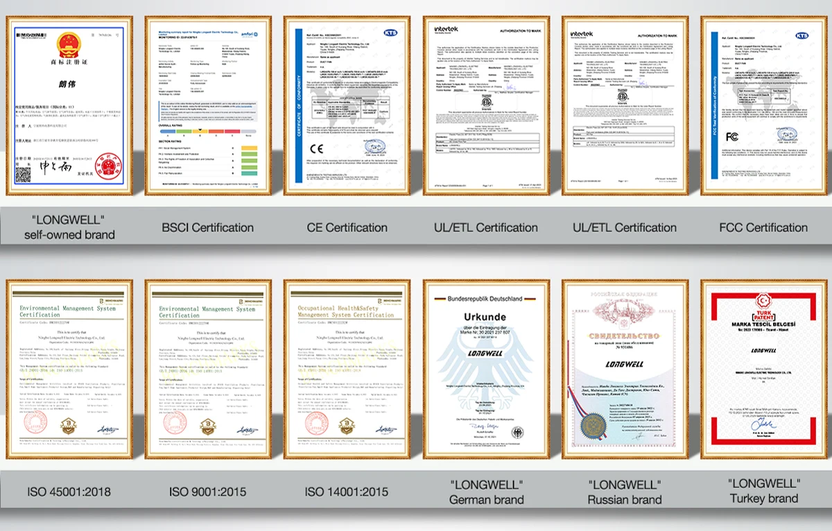
Complete Range of Professional & Certified
LONGWELL fans are independently certified to international quality, safety and energy-efficiency standards.

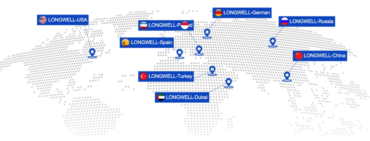
Global Market & Client Preference
The LWSWF series is specified by commercial building contractors and clients across Europe, the Middle East, Southeast Asia and the Americas.
Related Products
Explore other LONGWELL industrial and mixed flow fans for diverse pressure, airflow, and exhaust requirements.
LWERC Series External-Rotor Energy-Saving Centrifugal Fan
Compact external-rotor centrifugal blower engineered for energy-saving cabinet and ducted ventilation.
View Product →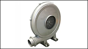
LWMPF Middle Pressure Blower
Cast-housing medium-pressure centrifugal blower for industrial air supply, combustion, and material conveying.
View Product →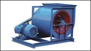
LWFDF4-79A / 4-2X79E Centrifugal Fan
High-volume single and double-inlet centrifugal fan for large-scale building and plant HVAC systems.
View Product →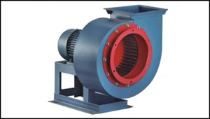
LWKXF Oil-Smoke Exhausting Centrifugal Fan
Box-type low-noise centrifugal exhaust unit built for commercial kitchen fumes and inline duct extraction.
View Product →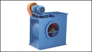
LWFDF11-62 Low-Noise Multi-Vane Centrifugal Fan
Forward-curved multi-vane centrifugal fan designed for low-noise kitchen exhaust and general ventilation.
View Product →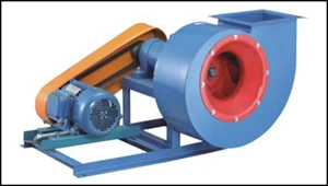
LWFDF6-48 Dust-Exhausting Centrifugal Fan
Wear-resistant centrifugal fan engineered for wood chips, dust collection, and particulate-laden air streams.
View Product →Frequently Asked Questions
Quick technical answers about the LWSWF mixed flow fan series.
What is the advantage of a mixed flow fan over an axial or centrifugal fan?
Mixed flow fans combine the aerodynamic traits of both. They deliver higher airflow volumes similar to axial fans, but generate greater static pressure capabilities akin to centrifugal fans, making them ideal for overcoming resistance in long, straight duct runs.
What do the S, T, and H designations mean in the LWSWF series?
The S series represents the standard single-speed models. The T series features a two-speed motor for variable ventilation demands. The H series is optimized for higher static pressure outputs.
How is this fan installed into an HVAC system?
The fan features an inline tubular design with standard flanged connections on both the inlet and outlet, allowing it to be bolted directly between sections of circular ductwork. A sturdy mounting foot secures the assembly.
What are the common applications for this fan?
It is widely utilized for general ventilation and air exchange in large commercial properties, hotels, office buildings, cold storage facilities, and industrial factory workshops.
Need a Quote or Custom Specs?
Send us the air volume, total pressure, and installation layout. Our engineers will match the right LWSWF model and reply within 24 hours.