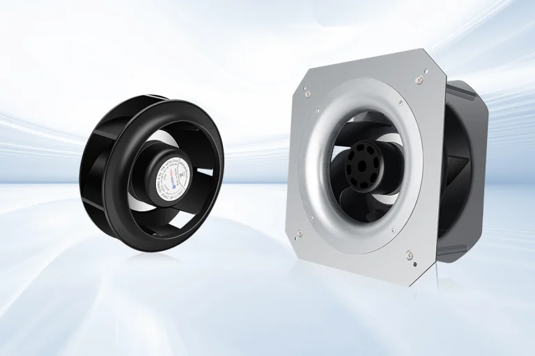
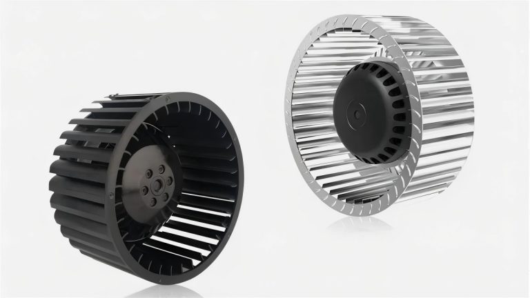
As HVAC system meets increasingly stricter efficiency requirements, EC motor fans have become an important solution for high-efficiency air movement. One commonly cited figure is up to 92% efficiency. What does 92% figure mean? How can an EC motor fan reach 92% efficiency? This article reveal facts behind EC motors and also tell you how to order EC motors from manufacturers.
What is EC motor?
The EC motor combines alternating current (AC) and direct current (DC) voltages to deliver exceptional energy efficiency. EC motors use electronic communication to manage the motor’s rotation and provide high motor efficiency, reduced mechanical losses, and precise speed control.
When EC motors are paired with an optimized fan impeller and aerodynamic design, the result can be a highly efficient complete fan assembly.
What the 92% Efficiency Actually Measures?
Before comparing any numbers, establish what is inside the measurement boundary. Fan marketing uses at least four different efficiency values, and they are not interchangeable:
- Motor efficiency (ηmotor): shaft power delivered to the impeller divided by electrical power into the motor. This is the value most often quoted as “up to 92%”. It is measured at a specific speed, torque and temperature — typically the best point.
- Controller (drive) efficiency (ηctrl): the share of electrical power that survives rectification, inversion and commutation. A good integrated EC drive runs at 95–97%.
- Impeller / fan aerodynamic efficiency (ηfan): useful air power (airflow × total pressure rise) divided by shaft power. Well-designed backward-curved impellers peak around 70–80%.
- Wire-to-air efficiency (ηwire-to-air): useful air power divided by total electrical input. This is the product of the three values above and the only number that predicts energy bills.
The arithmetic matters. Take a 1.1 kW input EC fan with a good drive (96%), a 92% motor and a realistic 70% impeller: wire-to-air efficiency is 0.96 × 0.92 × 0.70 ≈ 62%. Both statements — “92% efficient motor” and “62% wire-to-air fan” — describe the same physical fan. Neither is dishonest, but they answer different questions.
Motor efficiency also scales with size. A 30 W EC motor typically peaks near 70–80%, a 200 W motor near 85%, and only motors from roughly 500 W upward enter the 90%+ region where a 92% claim is credible. If a supplier quotes 92% for a small fan, ask which boundary and which test produced the number.
Where the Energy Goes: A Loss Budget
The clearest way to understand EC efficiency is to walk the loss budget of a typical mid-size EC centrifugal fan at its best point:
| Loss mechanism | Where it occurs | Typical share of input power |
| Stator copper loss (I²R) | Resistance of the winding at operating temperature | 2–4% |
| Iron loss | Hysteresis and eddy currents in the laminated stator core | 1–2% |
| Rotor loss | ≈0 — the magnet rotor carries no induced current | Near zero (10–20% of total losses in an induction motor) |
| Friction and windage | Bearings, air drag on the rotating parts | 0.5–1% |
| Stray load loss | Leakage flux and high-frequency effects under load | 0.5–1% |
| Controller loss | MOSFET conduction and PWM switching in the drive | 2–4% |
| Aerodynamic loss | Impeller flow separation, turbulence, casing and inlet losses | 25–35% — the dominant item |
Why Are EC Motors Highly Energy Efficient?
The Permanent-Magnet Rotor
An AC induction motor creates its rotor field by induction: the stator field sweeps past the rotor, inducing currents in the rotor cage, and those currents produce the torque. Induction only works if the rotor slips behind the field, and every amp induced in the cage becomes heat. Rotor losses typically account for 10–20% of total losses in a small induction motor, and they rise badly at part load.
An EC (electronically commutated) motor takes a different route. The rotor field comes from permanent magnets, so the rotor needs no induced current, produces no rotor I²R heat, and runs cool by design. The rotor turns in lockstep with the rotating stator field, so there is no slip and speed equals commanded frequency. This is also what makes precise speed control trivial.
Electronic Commutation and Drive Electronics
Because the EC rotor carries its own field, the electronics decide where the stator field points and when. The drive rectifies mains AC to DC, then a three-phase inverter sequentially energizes the stator phases. The efficiency-relevant factors include commutation strategy, switching loss, position sensing, and input power factor.
The integrated drive also brings the operational features that make EC fans economical in the field: soft start (no 4–8× inrush current of a direct-on-line induction start), native 0–10 V / PWM / Modbus speed control, and protective functions (stall, over-temperature, over/undervoltage) that prevent the failures that destroy efficiency unnoticed.
Impeller Aerodynamics and the Operating Point
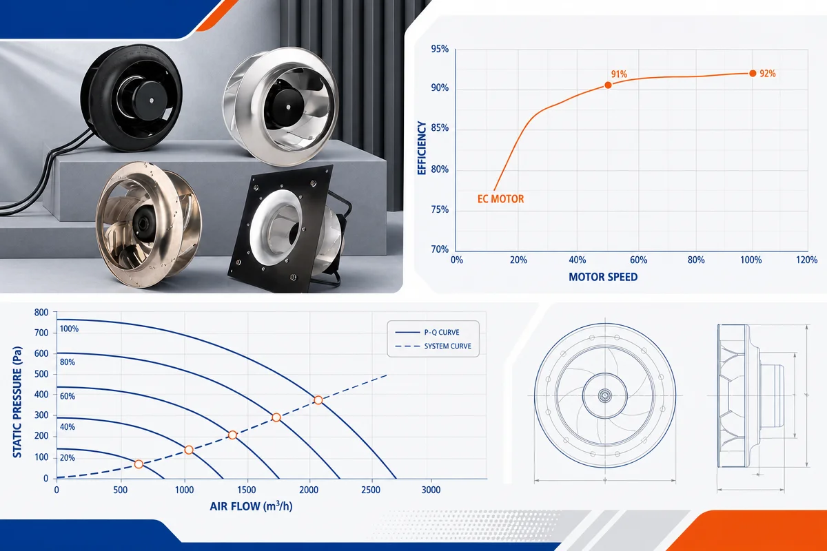
The motor is necessary but not sufficient. Wire-to-air efficiency peaks when the duty point — the intersection of the fan curve with the system resistance curve — lands near the impeller’s best efficiency point (BEP). There, flow attaches cleanly to the blades and most shaft work becomes useful pressure.
As a working rule, keeping the duty point within roughly ±15% of the BEP flow keeps aerodynamic efficiency near its peak. This is why LONGWELL selection always starts from the duty point (airflow + static pressure), not from a frame size.
EC vs AC Induction
| Aspect | AC induction (external-rotor / capacitor-run) | EC (permanent magnet + integrated drive) |
| Peak motor efficiency (small fan sizes) | ≈ 50–70% | ≈ 80–92% |
| Efficiency at part load | Falls away sharply below rated load | Remains high across ~30–100% of speed |
| Speed control | Needs external VFD (cost, losses, wiring) | Native 0–10 V / PWM / bus, no extra hardware |
| Power factor | ≈ 0.75–0.85 | ≈ 0.98–1.0 |
| Speed accuracy | Slip varies with load and voltage | Synchronous, held by closed-loop control |
| Maintenance | Bearings only | Bearings only — no brushes, no commutator |
| Purchase cost / lifecycle cost | Lower purchase cost | Higher purchase cost, typically lower lifecycle cost on running hours |
Verification Checklist for Buyers
| What to request | Why it matters |
| Full performance curve at the intended speed | Shows whether the duty point sits near the BEP or on the degraded part of the curve |
| Measured input power at the duty point | The single number that drives energy cost; immune to efficiency-boundary ambiguity |
| Stated efficiency boundary | Confirms whether the figure is motor, drive, or wire-to-air |
| Test standard and method reference | Makes numbers comparable between suppliers (ISO 5801 / AMCA 210) |
| Sound power at the duty point | Efficiency traded against noise is a poor trade in occupied spaces |
| Speed control interface and turndown range | Determines achievable part-load savings on the actual system |
| Motor protection class, insulation class, temperature rating | Ensures the efficiency survives the installed environment, not just the lab |
Engineering Notes
A 92% value is meaningful only when the supplier states what is being measured. Motor efficiency can be higher than complete fan wire-to-air efficiency because the impeller and controller also introduce losses.
EC technology reduces losses through permanent magnets and electronic commutation. Good aerodynamic design then turns that motor advantage into useful airflow rather than heat and noise. The permanent-magnet rotor removes the rotor losses that are structurally unavoidable in induction machines; sinusoidal commutation and low-loss switching keep the electrical chain in the mid-nineties; the impeller and the operating point then decide most of what remains.
For LONGWELL replacement work, the most practical comparison is the measured power at the same airflow and static pressure as the original fan. If the replacement draws less power at the same duty point, every efficiency question has already been answered in the only units that matter.