Chassis Constraints for the Air Handler
First, a customer needed an air handler cross flow fan for a new commercial unit. They came to us with an
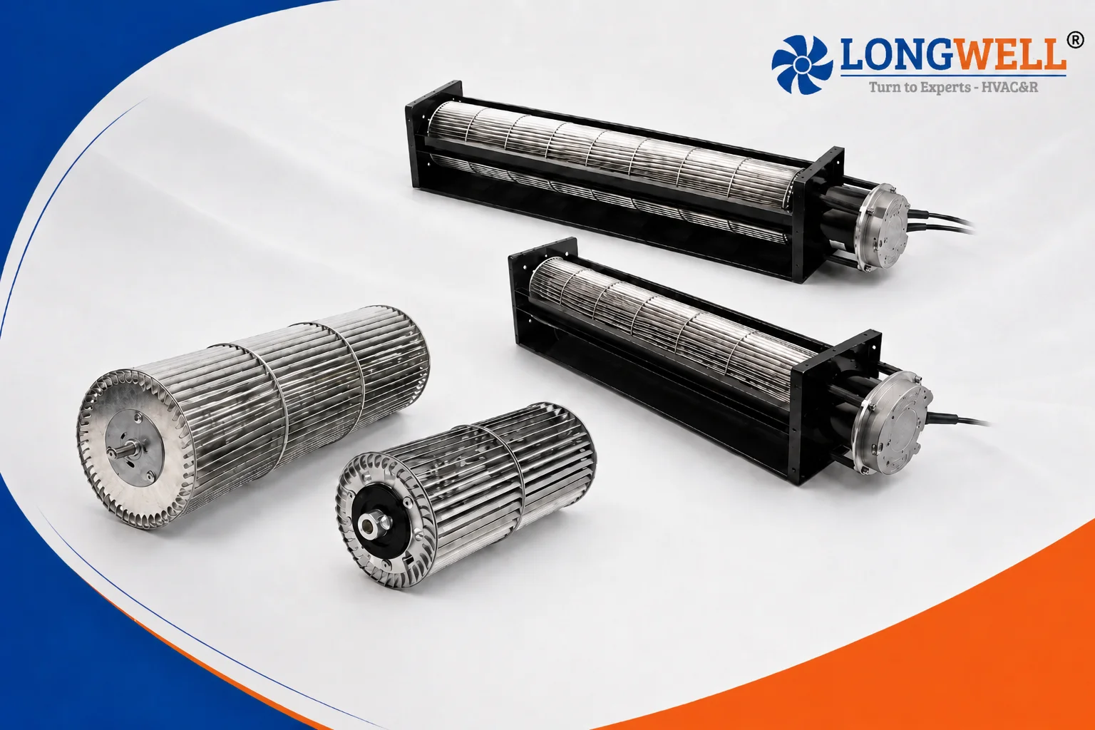
EC cross flow fan for a new commercial air handler. The cabinet set strict limits, so the air handler cross flow fan had to fit what already existed. Next, the internal gap allowed a maximum cross-section of 130 by 130 mm. The air handler cross flow fan could not exceed 635 mm in total frame length. Furthermore, the sheet metal already had mounting holes at exactly 550 mm, and the air handler cross flow fan had to meet them. This physical gap became our primary design limit.
Meanwhile, the thermal load required high performance. The fan had to move 640 m³/h of air. It needed to overcome 74 Pa of static pressure. Also, the acoustic noise could not exceed 53 dB(A). Therefore, the unit had to run smoothly without screaming at high speeds. Finally, outdoor conditions forced a harsh temperature range. The system had to start reliably at -25°C. Even so, it needed a lifespan of 40,000 hours at a 40°C ambient temperature.
The power supply was standard 230V at 50 or 60 Hz. Consequently, the fan had to accept this main line voltage directly. The customer also wanted direct logic control. The main board outputs a 0-10V or PWM signal. Thus, the motor needed built-in electronics to read this command. Furthermore, the factory required parts tested to strict methods. We test to AMCA 210-16 methods for airflow accuracy. The design also had to follow GB/T1804-v tolerance rules.
Engineering Choices for the Air Handler Cross Flow Fan
We studied different blower designs to meet these rules. First, we considered a basic AC motor setup. However, an AC motor cannot read a 0-10V signal directly. It requires a bulky variable frequency drive.
Therefore, we rejected the AC motor to save space and reduce wiring. Instead, we selected an external rotor EC motor. We picked the EC72 frame, rated at 85W.
Sizing the Air Handler Cross Flow Fan Impeller
Next, we had to define the moving parts. The standard catalog version of this unit has a 360 mm wheel. We could spin that short wheel very fast to move 640 m³/h. By contrast, high speeds create severe air noise.
It would easily break the 53 dB(A) limit. So, we stretched the impeller to 500 mm. This longer wheel uses 35 aluminum alloy blades. It pushes a wide sheet of air slowly.
In short, it hits the flow target at just 1500 RPM. The long wheel rests on an 8 mm steel shaft. Also, it uses an 8 mm bushing for smooth rotation. We selected ball bearings over sleeve bearings.
First, ball bearings handle cold weather better. Next, they survive much longer in continuous operation. This ensures the unit meets its 40,000-hour life goal. Meanwhile, the iron housing plates hold the motor firmly.
The side plates measure 50 mm by 50 mm at the mounting tabs. Consequently, the metal shell does not flex under air pressure.
Wiring and Material Costs
This choice carried a materially higher cost. First, the custom 500 mm aluminum wheel costs more to make. Next, we had to form custom iron side plates and air inlet plates. This added significant weight.
Also, the EC motor required a complex 500 mm cable harness. The wiring includes a brown line for power and a blue line for neutral. Furthermore, it needs a yellow and green wire for PE grounding. The control uses red, blue, yellow, and white lines for the 0-10V and speed signals.
Finally, the finished unit draws just 27W of power. It meets all GB/T13933-2008 safety codes.
Technical Specifications
| Model | LWCE-90360SN-06-00 |
| Air Volume | 640 m³/h |
| Static Pressure | 74 Pa |
| Speed | 1500 ± 150 RPM |
| Input Power | 27 W |
| Motor Frame | EC72 (85W) |
| Voltage | 230 V |
| Frequency | 50/60 Hz |
| Overall Dimensions | 633 ± 3 mm (L) x 130 mm (W) x 130 mm (H) |
| Impeller Dimensions | ø 90 x 500 mm |
| Noise Level | 53 dB(A) |
| Operating Temperature | -25°C to +60°C |
| Bearings | Ball bearing |
| Insulation Class | Class B |
| Speed Control | 0~10V / PWM |
The 550 mm mounting dimension controlled the entire physical design. Meanwhile, the 0-10V speed control row defined the electrical setup. Therefore, the customer avoided buying separate motor drives.
Reference: AMCA 210 covers the test method behind these figures.
Technical Documentation
longwell-lwce-90360sn-06-spec-sheet-01.pdf
This engineering drawing shows the custom 633 mm housing length and the precise 500 mm cable harness wiring colors.
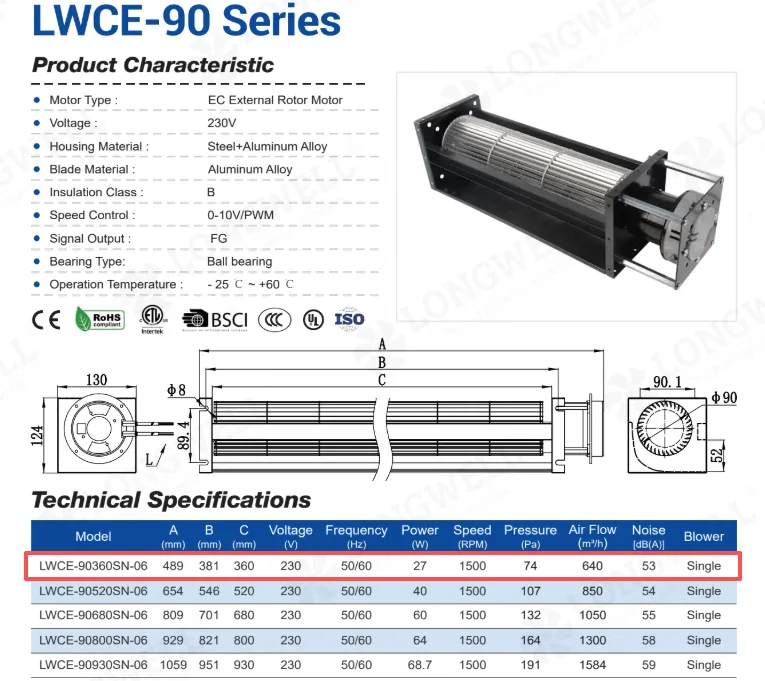
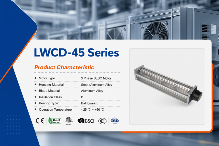
The catalog data lists the base model specifications, highlighting the 74 Pa pressure and 27W power rating.
Fixing Similar Space Constraints
When you specify an EC cross flow fan for a tight enclosure, minor details dictate the success of the project.
- First, measure the exact hole distance on your metal chassis. In this case, the 550 mm gap forced a complete housing redesign. A standard model would not bolt in.
- Next, balance your noise limits against the wheel length. If you restrict the length, the wheel must spin faster. Therefore, it will make more noise. A longer wheel running slower is always quieter.
- Also, confirm your logic board voltage. Connecting a 0-10V output directly to a smart motor saves major wiring headaches. Consequently, you save space on your main control panel.
- Finally, check your temperature ranges. Because we build these units with ball bearings, they start cleanly at -25°C. A cheaper sleeve bearing might freeze in outdoor equipment.
Related: Cross Flow Fans.
Frequently Asked Engineering Questions
Technical Documentation & Resources
Browse our cross-flow fans range, the AC cross-flow fans section, or cross-flow impellers.
Have a Similar Fan Requirement?
Longwell’s engineering team delivers custom spec sheets and samples within 90 days. Since 1990, we have supplied EC fans and blowers to OEMs across HVAC, cold chain, data center, and industrial applications worldwide.
Browse Related Products:
🏆 ISO 9001 / ISO 14001 / ISO 45001 | CE (TÜV) | UL/ETL | ATEX Zone 21/22 | AMCA 210-16 / ISO 5801 tested