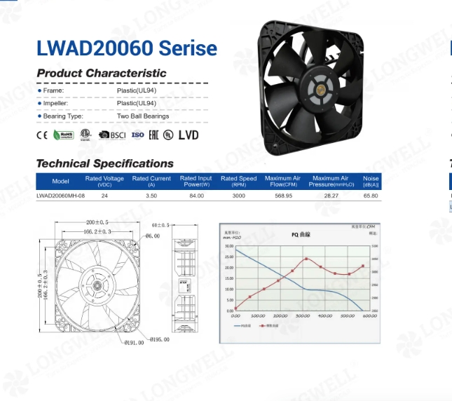
Designing a Custom cross flow fan rotor hub
First, an HVAC client in India sent us a big request. They needed a direct replacement cross flow fan rotor hub. They use this part to stop vibration in their blower units. Next, the volume numbers were very large.
The customer orders two million parts each year. They want 200,000 parts shipped every month. Therefore, we had to build a very stable mold. We could not risk early mold wear during the run.
Furthermore, they gave us strict rules for the part shape. The drawing showed a total length of exactly 20 mm. The outer metal flange was exactly 0.8 mm thick. Meanwhile, the outer width measured 48 mm.
The inner bore hole was exactly 8 mm across. Also, this hole needed a tight 8H8 tolerance fit. Finally, the rubber part had strict chemical limits. The client asked for pure chloroprene rubber.
They needed a JIS45 hardness score. Even so, the part had to pass an A20 tension test. In short, the rubber could not peel away from the metal sides. This rule forced us to focus heavily on the bonding process. Next, we checked the AMCA 210-16 methods to ensure the cross flow fan rotor would test well later.
Choosing Materials and Adhesives
First, we looked at stock rubber mounts in our factory. However, none of them had the exact 0.8 mm flange. None had a 20 mm total length. Instead, we chose to cut a brand-new mold.
This choice added a small tooling cost up front. But, it was the only way to meet the exact sizes. Next, we had to pick the right rubber compound. Many fan makers use EPDM to save raw material money.
We rejected EPDM for this specific job. Instead, we used pure chloroprene rubber. Chloroprene handles heat and oil much better. Therefore, it lasts longer in hard factory settings.
This choice led to a materially higher cost per part. Yet, it met the drawing rules perfectly and protected the system.
Bonding the cross flow fan rotor hub
Next, we faced a major chemical problem. We had to stick the rubber to an aluminum core. We also had to stick it to a galvanized steel plate. If the bond fails, the motor torque will tear the part.
So, we used a special two-part glue process. First, we coated the metal with CHEMLOCK205 primer. Next, we applied CHEMLOCK6125 as the top layer. As a result, the rubber bonded firmly during the baking process.
The final part easily passed the A20 tension test. Furthermore, the rubber hit a tensile strength over 100 kgf/cm2. Finally, we had to prevent fan wobble. We machined the aluminum core flat.
We kept the runout limit under 0.2 mm. This extra step added a bit of machine time. However, it saved the final user from loud fan noise. It kept the blower wheel perfectly centered.
Technical Specifications
| Component Type | Rubber Boss / Rotor End Ring |
| Rubber Material | Chloroprene (CR / Neoprene) |
| Core Material | Aluminum |
| Flange Material | Galvanized Sheet |
| Rubber Hardness | JIS45 ±5 |
| Tensile Strength | ≥ 100 kgf/cm2 |
| Elongation Rate | ≥ 400% |
| Outer Diameter | 48 mm |
| Bolt Circle | 38 mm |
| Inner Bore | 8 mm (8H8) |
| Total Length | 20 mm (±0.2) |
| Flange Thickness | 0.8 mm |
| Plane Deviation | Under 0.2 mm |
First, the 8H8 hole tolerance is the most crucial detail here. Next, the 0.2 mm plane limit matters just as much. Together, these two numbers ensure the cross flow fan rotor wheel spins smoothly on the motor shaft.
Reference: ISO 21940 covers the test method behind these figures.
Technical Documentation
Longwell Production Drawing LW-C03-80-06
First, this approved PDF shows the exact chemical glue standards and size rules for our factory.
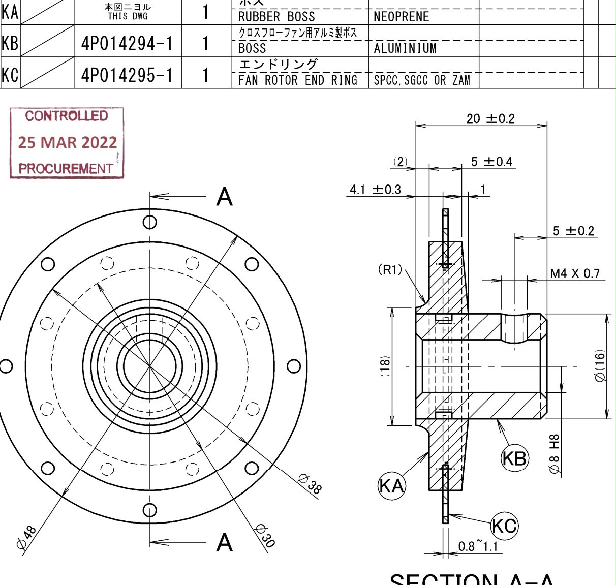
Next, this image shows the metal layers and the rubber filling inside the central core.
Advice for Sourcing Rubber Dampers
If you need a new cross flow fan rotor hub, you must check several details first. Mistakes here will ruin your blower assembly and cause huge delays. Therefore, engineers should verify these points before asking for a price.
- First, pick the exact rubber type for the job. You must tell the factory if you need EPDM, natural rubber, or chloroprene. The wrong rubber will melt or crack in hot air.
- Next, share the exact metal sizes on your drawing. The 0.8 mm outer ring in this project allowed the hub to snap into place easily. Small errors here cause assembly lines to jam.
- Furthermore, set a hard limit for surface wobble. A runout limit under 0.2 mm keeps the fan wheel spinning quietly. It stops the motor bearings from breaking early.
- Finally, ask your supplier about their chemical glue process. We use specific primers so the part passes strict tension tests. Rubber injected without glue will fail under load.
Related: Cross Flow Fans.
Common Engineering Questions
Technical Documentation & Resources
Browse our axial fans range, the AC axial fans section, or EC axial fans.
Have a Similar Fan Requirement?
Longwell’s engineering team delivers custom spec sheets and samples within 90 days. Since 1990, we have supplied EC fans and blowers to OEMs across HVAC, cold chain, data center, and industrial applications worldwide.
Browse Related Products:
🏆 ISO 9001 / ISO 14001 / ISO 45001 | CE (TÜV) | UL/ETL | ATEX Zone 21/22 | AMCA 210-16 / ISO 5801 tested