Fan motor bearing plays an essential role in supporting metal shaft rotating. It also reduce friction so that the blade can operate well. Inadequate maintanance of fan motor bearings can cause severe friction and excessive heat generation. If your fan motor bearing shows the signs of never operates well, timely inspection and replacement are important to avoid costly equipment damage.
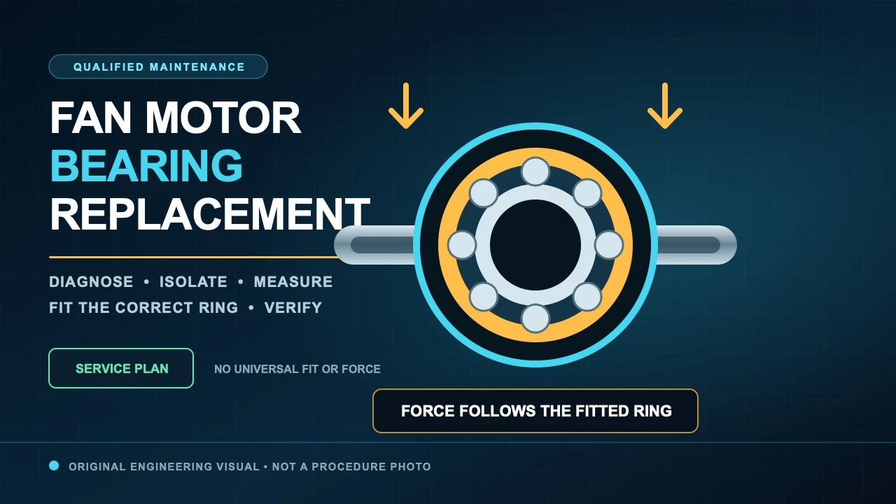
This guide is written for qualified maintenance personnel. It explains the decision sequence, force path and verification records behind a defensible fan motor bearing replacement. It is not a universal bearing number, fit table, heating temperature or authorization to work on energized equipment.
Confirm the bearing diagnosis and the service boundary
Sound alone is weak evidence. Impeller rub, loose mounting, imbalance, belt noise, airflow turbulence, an electrical tone and structural resonance can all be mistaken for a damaged bearing. Compare the symptom with vibration, temperature, shaft movement and the as-found operating condition. If the evidence still points to the bearing, check whether the motor manufacturer permits field replacement.
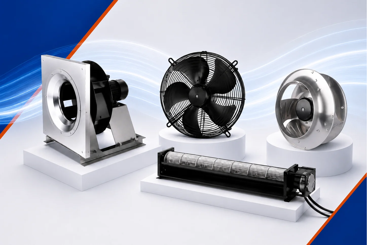
Some sealed or integrated motors, permanent-magnet assemblies, hazardous-location products and life-safety fans require an approved repair facility or complete assembly replacement. The broader AC fan motor overview helps identify the motor context, but the exact model drawing, parts list and service manual govern the work.
Isolate every energy source and support the rotating assembly
Use the site’s hazardous-energy procedure before removing a guard, cover, wheel, pulley or end bell. Isolate electrical power, control and automatic-start circuits, backup sources and any mechanical or pneumatic energy. Verify the de-energized state with the approved instruments and confirm zero rotation. A control-panel stop command is not an energy-isolating device.
Plan the lifting and support points before fasteners are released. A heavy rotor, wheel or motor can shift unexpectedly and create crush or pinch hazards. Rated supports and an exclusion zone should carry the load; hands, pry bars and improvised blocks should not.
Preserve the as-found state and identify the complete bearing
Record wiring, rotation, end-bell orientation, impeller position, spacers, shims, wave washers, retaining rings and measured clearances before disassembly. Mark components only where the service procedure allows it. Keep the removed bearing clean and labeled so its raceways, grease and damage pattern remain available for root-cause review.
Match the full bearing designation, not just bore and outside diameter. Suffixes can define internal clearance, seals or shields, cage, precision, grease, temperature range and electrical insulation. Also confirm shaft speed, load direction, fit, environment and lubrication policy. A visually similar bearing can be the wrong engineering part.
Measure the seats before selecting a removal method
Inspect and measure the shaft seat, housing bore, shoulders, fillets and retaining features against the model-specific tolerances. Check for fretting, burrs, corrosion, wear, distortion and runout. If the seat is damaged, stop and use the approved repair disposition. Peening, random shims, adhesive, grinding or extra press force are not substitutes for the specified fit.
The measurements also reveal which ring carries the interference fit. That fact determines the safe force path. It should be established from the design and measurements, not guessed from whichever surface is easiest to reach.
Apply removal and installation force through the fitted ring
Use a correctly rated, aligned puller or press with purpose-made support. Removal force acts on the ring being removed from its tight seat. During installation, force is applied to the ring with the interference fit; when both rings are fitted at the same time, the approved tool must support both ring faces evenly. Transmitting force through the balls or rollers can indent raceways and damage a new bearing before the motor runs.
If thermal mounting is authorized, use controlled equipment and the bearing manufacturer’s limits. Open flame and uncontrolled local heating are excluded. Direct hammering, chisels, loose sockets, pipe offcuts and unguarded pullers add impact, misalignment and projectile hazards rather than control.
Control cleanliness, lubrication, preload and endplay
Keep the work zone clean and open new bearings only when installation is ready. Use the specified lubricant, quantity and application point. Many sealed bearings are prelubricated and should not receive added grease; relubricatable designs need a compatible product and a defined purge path. Mixing unknown greases or filling every void can create heat and seal damage.
Restore every spring, washer, shim, locknut, spacer and retainer in the documented orientation. These parts may control rotor position, preload or endplay. Use specified torque and locking parts, then verify free rotation and clearances by the manufacturer’s safe method before power is restored.
Correct the cause and rebuild the complete fan
A new bearing will not correct misalignment, imbalance, bearing current, overload, excessive heat, contamination or a damaged fit. Use the removed part and operating evidence to investigate the failure chain. Recheck the shaft, rotor, windings, grounding path, cooling passages and adjacent components within the approved scope.
Impeller or pulley removal can change alignment, axial position, runout and balance. Restore the assembly to the drawing and verify wheel-to-inlet and wheel-to-housing clearances. For related inspection context, see LONGWELL’s centrifugal fan maintenance checklist.
Finish with guarded acceptance and a repair passport
Restore grounds, terminals, covers, guards, interlocks and cooling paths before the first run. Remove tools and loose parts, clear personnel and follow the approved test sequence. Evaluate direction, current, temperature, vibration, sound and operating duty only at declared measurement points and against manufacturer limits or a valid baseline.
The repair record should link the motor and bearing identities, measured fits, lubricant, retained components, assembly checks, root-cause action and acceptance results. That “repair passport” makes the job traceable and gives the next technician evidence instead of assumptions.