EC fans have become the preferred choice for modern HVAC, industrial ventilation, data centers, cleanrooms, and OEM equipment due to their superior energy efficiency, intelligent speed control, and lower lifecycle costs. Selecting the right EC fan involves much more than matching airflow – it requires evaluating system resistance, fan type, motor performance, control methods, environmental protection, and project lead time.
This guide presents LONGWELL’s 7-step EC fan selection process, a practical engineering framework that helps you move from your required airflow (CFM or m³/h) and static pressure (Pa) to a fully specified EC fan solution. Trusted by 1,000+ HVAC manufacturers, data center designers, OEM equipment builders, and industrial system integrators, this engineering guide can reduce weeks of specification revisions and supplier back-and-forth.
For: HVAC engineers, MEP consultants, OEM thermal teams, data center cooling architects, retrofit specialists
7 Steps to Choose the Right EC Fan
Follow these seven engineering steps to identify the optimal EC fan for your application.
Step 1: Define the Duty Point (Airflow + Static Pressure)
Every fan selection starts with one operating point. Get this right and the rest cascades. Get this wrong and you’ll oversize/undersize for the next 10 years.
AIRFLOW CALCULATION
Sensible heat load: Q (kW) = m × cp × ΔT, where m = mass flow, cp = 1.006 kJ/kg·K for air, ΔT = supply-return temperature delta.
Volumetric airflow: V (m³/h) = Q / (1.2 × 1.006 × ΔT) × 3600. Use ΔT = 10K for office HVAC, 12K for data center CRAH, 8K for residential.
| Element | Typical Pa range | Notes |
| Filter | 50–250 Pa | G4 = 80 Pa clean / 250 Pa dirty; F7 = 200 Pa clean / 400 Pa dirty |
| Heating/cooling coil | 100–400 Pa | Depends on rows, face velocity |
| Damper | 30–100 Pa | |
| Ductwork friction | 200–500 Pa | Depends on length, diameter, aspect ratio |
| Diffuser/terminal | 50–150 Pa |
Step 2: Select the Appropriate Fan (LONGWELL Series)
Choosing the right fan type is essential to achieving the required airflow, static pressure, energy efficiency, and acoustic performance. Different ventilation applications demand different aerodynamic designs, so selecting the appropriate fan series early helps optimize both system performance and lifecycle costs.
LONGWELL offers a comprehensive portfolio of EC fan solutions for HVAC, refrigeration, industrial ventilation, data centers, air purification, and OEM equipment. Use the following brief recommendations to identify the most suitable fan series for your application.
| Total Pa | Fan family | LONGWELL series | Typical applications |
| < 400 | Axial EC | LWAE3G | Condenser, dry cooler, free cooling coil, large ventilation duct |
| 400–1,800 | Backward-curved EC plug | LWBE3G | AHU, CRAH, FFU, RDHx, in-row, heat pump, BESS |
| 1,800–3,200 | High-pressure EC plug | LWHV | Liquid-cooling CDU, dust collector, dense HX |
| Compact + low Pa + high CFM | Forward-curved blower | LWFC | Residential AHU, fan coil unit, small ERV |
| Straight duct, low Pa, indoor | Mixed-flow inline | LWM | Residential ducted ventilation, ERV/HRV core |
| Wide even flow, fan coil indoor unit | Cross-flow | — | AC indoor unit, slim fan coil, elevator |
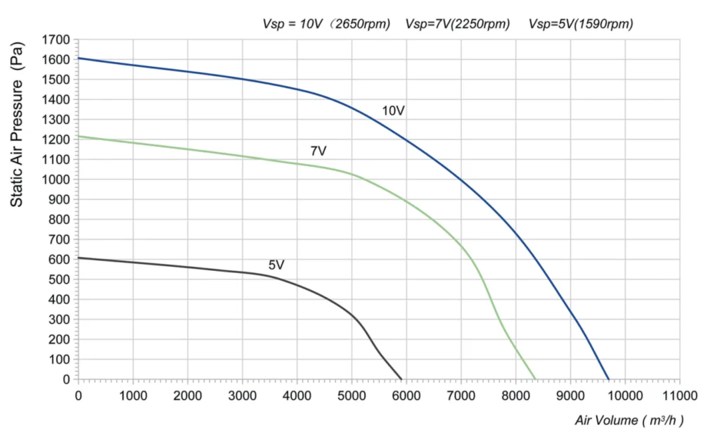
Step 3: Determine Fan Size Using the Performance (P-Q) Curve
Pick the smallest diameter that crosses your duty point above the 80%-BEP line. This maximizes efficiency, minimizes noise, and reduces cost. Oversizing diameter “for safety” is the #1 selection mistake. It pushes operating point left of BEP → instability, increased noise, 20–40% energy waste. EC fans modulate down — the part-load efficiency curve is flatter, not zero-cost.
Rules of Thumb (Ø vs CFM, Backward-Curved Plug)
| Diameter | Max m³/h |
| Ø250 | up to 2,400 |
| Ø310 | 3,500 |
| Ø355 | 4,500 |
| Ø400 | 5,800 |
| Ø500 | 8,200 |
| Ø560 | 10,500 |
| Ø630 | 13,000 |
| Ø710 | 16,500 |
| Ø800 | 20,500 |
| Ø900 | 26,000 |
Step 4: Match the Motor Power and Electrical Requirements
Voltage is regional — don’t assume. North America = 480V 3Φ 60 Hz + UL; EU = 400V 3Φ 50 Hz; Data center DC = 48/380 V DC. Verify with electrical engineer.
Verify motor full-load amps fit panel breaker and contactor sizing.
Voltage Cheatsheet
| Region / Application | Standard voltage | Notes |
| EU / UK / AU / SG | 230 V 1Φ or 400 V 3Φ (50 Hz) | Standard commercial HVAC |
| North America | 208 V or 480Y/277V 3Φ (60 Hz) | UL-listed required |
| Telco / 5G / Data center DC | 48 V DC or 380 V DC bus | DC bus eliminates rectifier losses |
| Automotive / BESS | 24 V or 48 V DC | Low-voltage DC for compact enclosures |
| Asia / India | 220 V 1Φ or 415 V 3Φ | Verify local grid tolerance |
Step 5: Select the Appropriate Fan IP Protection Rating
Choosing the correct Ingress Protection (IP) rating is critical to ensuring long-term fan reliability. Many premature fan failures are caused not by the motor itself, but by moisture, dust, or corrosive contaminants entering the electrical and mechanical components. Selecting a higher protection level during the design stage typically costs far less than field replacements, warranty claims, and unexpected downtime.
- For outdoor HVAC equipment, condensers, heat pumps, and rooftop installations, specify IP55 or higher with UV-resistant coating to protect against rain, dust, and prolonged sun exposure.
- For coastal or offshore environments exposed to salt spray, choose IP67 models with corrosion-resistant materials and validated salt-spray protection.
- Dust environments need ATEX, not just IP. Combustible dust (grain, sugar, pharma) → ATEX II 3D; hydrogen vent → ATEX II 3G.
- Cold chain needs anti-condensation heating, not just IP. Moisture ingress at −40°C = frozen bearings = dead fan.
| Environment | Required IP | Additional protection |
| Indoor AHU / CRAH / FFU | IP54 | Standard |
| Outdoor RTU / condenser / BESS container | IP55 | UV-resistant lacquer |
| Coastal / marine / food washdown | IP67 | ASTM B117 1000h salt spray |
| Cold chain / freezer −40°C | IP55 | Anti-condensation heating element |
| Grain / wood / sugar / pharma dust | ATEX II 3D Ex tc T125°C | LWBE3G-ATEX line |
| H₂ vent (BESS, EV battery thermal) | ATEX II 3G zone 2 | Custom OEM program |
Step 6: Choose the Right Control Protocol
The control protocol determines how your EC fan communicates with the HVAC equipment, Building Management System (BMS), or cloud platform. Selecting the right interface ensures seamless integration while avoiding unnecessary hardware costs, commissioning delays, and software complexity. The best choice is the one that matches your existing control architecture—not the one with the most features.
- 0–10 V Analog Control: For most HVAC applications, 0–10 V remains the simplest and most cost-effective control method. It is ideal for air handling units (AHUs), fan coil units (FCUs), heat pumps, and ventilation systems where only speed control is required.
- Modbus RTU: Modbus RTU is one of the most widely supported communication protocols for commercial HVAC systems. It enables fan speed control, operating status, fault reporting, and parameter adjustment through a Building Management System while keeping integration costs relatively low.
- BACnet MS/TP or BACnet/IP: Many commercial buildings specify BACnet as the standard communication protocol. If the project uses a BACnet-based Building Management System, selecting BACnet-compatible EC fans helps simplify commissioning and ensures compatibility with the building automation infrastructure.
- Modbus + MQTT: For IoT-enabled equipment, many manufacturers combine Modbus for local device control with MQTT for cloud connectivity.
- Zigbee and Matter: Wireless protocols such as Zigbee and Matter are primarily designed for residential and smart home applications. They are generally not recommended for commercial HVAC and industrial ventilation.
Over-specifying protocol adds cost + integration time with zero operational benefit. Match the protocol to the actual BMS, not to the “future-proofing” wish list.
| If your BMS / controller is… | Choose… | Why |
| Generic thermostat / simple PLC | 0–10 V analog | Cheapest, universal, no bus configuration |
| Niagara Tridium / Schneider | Modbus RTU | Native support, low integration cost |
| Niagara N4 / EcoStruxure IoT | Modbus TCP / BACnet IP | Ethernet eliminates RS485 wiring |
| Siemens Desigo / Honeywell WEBs | BACnet MS/TP or IP | Native object discovery |
| OEM with custom firmware | Custom Modbus map + MQTT | Full cloud + OTA control |
| Residential / smart home | Matter 1.2 / Wi-Fi / Zigbee | End-user app control, no installer |
Step 7: Confirm Lead Time and Finalize the Fan Model
In 2026 lead time matters as much as spec. Selecting the right EC fan is not only about achieving the required airflow and efficiency – it is also about ensuing the product can be delivered within your project schedule. In today’s supply chain environment, lead time has become a critical engineering and procurement consideration. Even the highest-performing fan can jeopardize a project if it cannot be delivered when needed.
Before releasing your final specification, verify the following factors:
- Product availability
- Sample lead time
- Production lead time
- Customization requirements
- Certifications and compliance
- Final part number (SKU)
- Prioritize Lead Time During Fan Selection
Many premium fan brands offer excellent performance but may require significantly longer manufacturing lead times, particularly for customized models. If your project has an aggressive construction or production schedule, selecting a readily available alternative can reduce project risk and accelerate delivery.
LONGWELL supports rapid product development with:
- Sample lead time: 1–3 working days
- Mass production lead time: 15–30 days for most standard product series
Once the fan model has been verified, finalize the complete product specification, including:
- Fan series and diameter
- Airflow and static pressure rating
- Motor power and voltage
- IP protection rating
- Communication protocol
- Mounting configuration
- Optional accessories and certifications
A fan that meets every performance requirement but cannot arrive on time may delay equipment production, commissioning, or project completion. Always evaluate performance, availability, and lead time together when making your final selection.
Engineering Tip: Request engineering samples as early as possible. Rapid sample delivery allows airflow testing, noise verification, and controller integration to begin immediately, reducing design iterations and helping bring your HVAC or OEM equipment to market faster.