
50-Fan CRAH FanGrid Retrofit · 2 MW Tier 3 Colocation
A composite reference case based on representative CRAH FanGrid retrofit projects in the colocation segment — replacing legacy belt-drive AC fans with EC plug-fan arrays for N+1 redundancy, lower PUE, and 4-week procurement vs 14–22 week European-premium lead time.
1 · Challenge
- Legacy belt-drive AC fans operating at 1.45 PUE — typical for pre-2018 CRAH installations.
- Original spec called for ebm-papst K3G500 RadiCal × 50, but 2026 lead time of 14–22 weeks blocked the colocation site's customer-commit move-in date.
- Site required N+1 redundancy (single-fan failure must not interrupt cooling), per-fan runtime telemetry to DCIM, and 24/7 operating envelope.
- Acoustic constraint <55 dB(A) at staff-walk-aisle adjacency.
2 · Solution Architecture
Bill of materials
| LONGWELL SKU | Type | Qty | Key spec |
|---|---|---|---|
| LWBE3G-500-EC | EC backward-curved plug fan | 50 units | Ø500 mm, 89% η, 38 dB(A) floor, IP54, 0–10 V + Modbus RTU master/slave |
| LONGWELLBUS gateway | Free cloud telemetry | 5 zones × 10 fans | Per-fan runtime, RPM, fault to DCIM via Modbus TCP |
3 · Modelled Outcomes — Typical Range
How to read these figures: the values below are modelled for this composite scenario — LONGWELL platform specifications combined with industry-standard improvement deltas for CRAH retrofits of this class. They are a planning range, not measured results from a single named project. Verified project data from real deployments is in Section 6.
4 · Implementation Timeline
5 · Engineering Lessons
- Lead time was the binding constraint, not peak η. The 2 pp η delta vs ebm-papst (89% vs 91%) was not visible in the annual energy bill because CRAH duty operates at 50–70% load most hours, where both fans hold flat η.
- Modbus master/slave parallel control with auto load redistribution on fault was the simplest path to JCI N+1 compliance without separate redundant fan banks.
- LONGWELLBUS gateway integration to Vertiv Trellis took 2 working days because the Modbus register map was published in advance — no custom BMS programming.
- Acoustic at 4 m staff aisle measured 47 dB(A) at 60% load (well under 55 dB(A) limit). Datasheet 38 dB(A) floor at 1 m proved out at install distance.
- Saturday/Sunday install cadence avoided customer downtime. Drop-in dimensional match to legacy mount allowed 4 CRAH per shift install rate.
6 · Verified Project Evidence
Unlike Section 3, everything below is drawn from actual project correspondence. Model numbers, duty points, quantities and the competitor units being replaced are stated as they occurred. Customer names are withheld; no pricing is published.
Abu Dhabi — Tier-3 data centre FanGrid, ebm-papst RadiPac replacement
- Replaced: ebm-papst K3G500-PB33-01 (RadiPac EC centrifugal module) in an existing FanGrid array.
- Supplied: LWBE3G500-218PT-06 — 400 V, 50/60 Hz, 5,700 W, 9.10 A, 15,000 m³/h, 1,900 Pa, 2,600 rpm, 87 dB(A).
- Physical constraint: had to fit the existing single-fan aperture of 1,305 × 805 mm and reuse the original power/control interface.
- What actually decided it: 3D models issued up front for interference checking, factory test certificates issued before collection, and exact pallet data (130 × 68 × 140 cm, 260 kg) for the MEP contractor’s logistics plan.
Russia — 16 AHU fan-wall systems, ebm-papst replacement
- System duty (customer’s own calculation sheet): 160,000 m³/h at 820 Pa total pressure, and a second array at 160,000 m³/h at 382 Pa.
- Replaced: ebm-papst K3G560-PB31-71 × 256 units and K3G450-PI86-01 × 320 units.
- Supplied for evaluation: LWBE560-PT-05 and LWBE450-PT-04, matched to 1.8 kW / 3 ph / 400 V / 50–60 Hz and the existing array geometry, with 0–10 V and Modbus control.
- Engineering issue solved: the customer had been sizing by impeller outer diameter while the array aperture is set by confuser diameter. A 630 mm confuser would not fit; the answer was a 515 mm confuser with a 655 mm impeller. This one distinction is the most common cause of a failed fan-wall retrofit.
- Also resolved: phase-loss relay behaviour. The customer’s bench test showed no relay transition; we published the full relay state matrix (normal / standby / phase loss / over-temperature / under-voltage) and confirmed the output requires no controller programming.
India — precision air conditioners (PAC), Ziehl-Abegg and Rosenberg replacement
- Replaced: Ziehl-Abegg and Rosenberg units of the same frame size in data-centre precision air conditioners.
- Supplied for evaluation: LWBE3G560-218PT-04 / -05, aluminium impeller, IP54, Class F insulation, S1 continuous duty.
- Acceptance condition: the end user required a 3–5 year warranty and would only qualify the fan after physical testing — so matching was done against the incumbent’s datasheet and P–Q curve plus installation topology, not on catalogue headline figures.
Russia — precision air-conditioning platform, full-range Modbus integration
- All EC backward-curved frames standardised on RS485 Modbus so the unit PLC could drive the whole range through one integration.
- Protocol versions mapped per drive hardware: LWRS485-02 for LWBE3G250-102PS-12 and LWBE3G310-102PT-09; LWRS485-03 for LWBE3G560-188PT-01 and LWBE3G630-188PT-06. Baud rate and register maps differ between the two — mixing them is a commissioning failure.
- Closed-loop speed registers (D101 / D106 / D107) documented against open-loop PWM so the unit could switch control modes without re-flashing.
- LWBE3G450-138PT-04 required an external Modbus module developed for this platform.
- Process lesson: when a panel change altered a suffix (LWBE3G250-102PS-07 → -12), the datasheet and protocol document were reissued immediately — a silent suffix change is what causes a comms mismatch on site.
Middle East — delivery performance on live projects
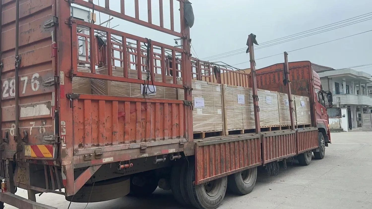
- 104 EC plug fans (42 pallets) consolidated onto a single direct flight to Dubai during peak air-freight season, rather than the planned split shipments, to hold an AHU builder’s production date.
- 960 EC fan motors supplied to an MEP contractor on a buyer-nominated forwarder collection.
- For a fan-wall unit project routed China → Germany (OEM performance test) → UAE site, Certificate of Origin, CE documentation and inspection reports were issued with the shipment; incomplete origin paperwork is the usual cause of a hold on this route.
- SGS factory audit report and STEP 3D models are issued as part of the selection package, which is what shortens vendor qualification on data-centre projects.
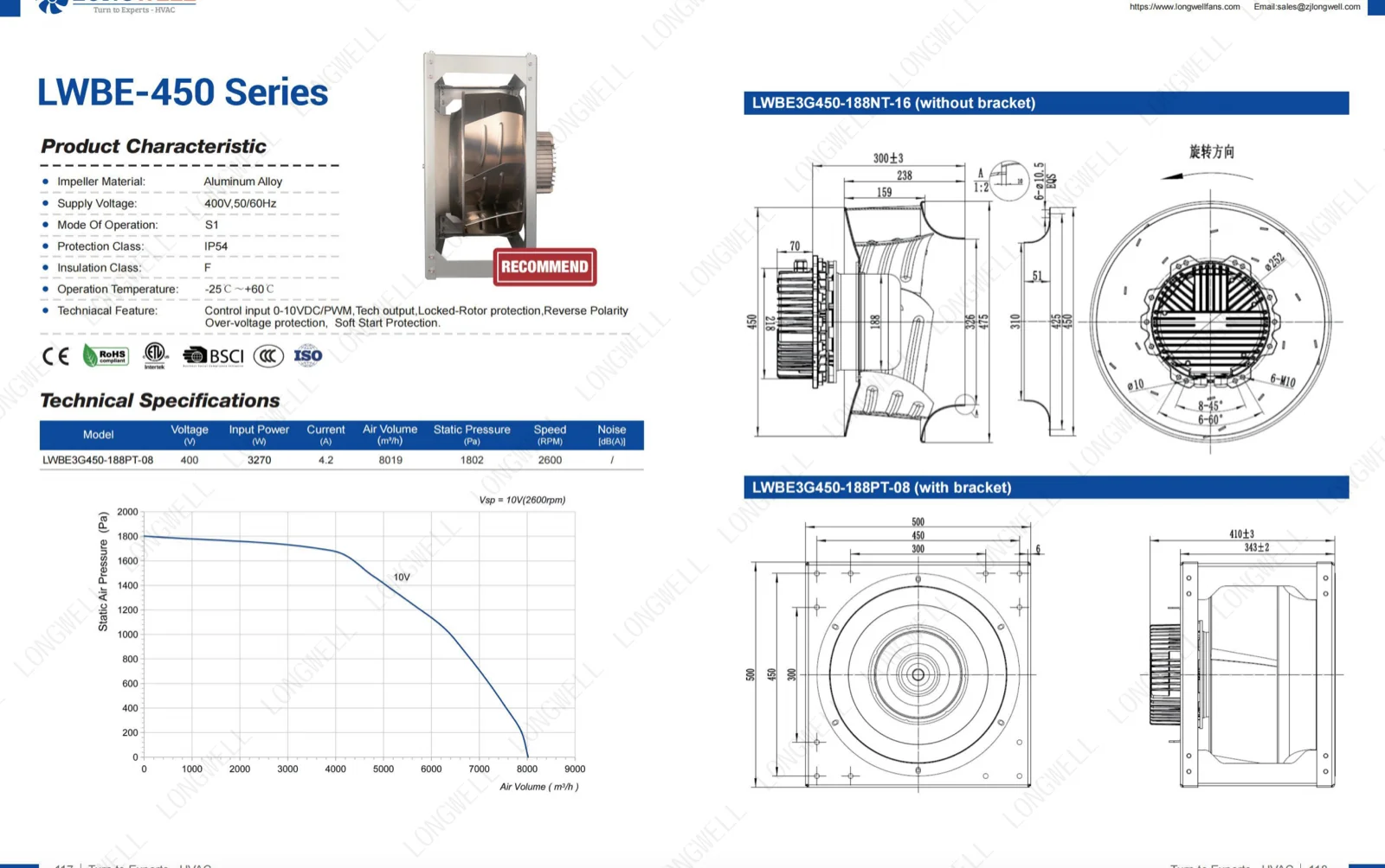
Fan performance figures are quoted from LONGWELL controlled datasheets and are tested per AMCA 210/211 methods; third-party reports available on request. EC versus AC energy saving is approximately 30%, higher under strongly varying load — confirm against your own load profile. Final selection must be confirmed against the actual duty point (airflow / static pressure / voltage / control method) and project validation.
Get a sized BOM for your project
Send your application duty point (CFM, Pa, ambient T, IP, certification scope). LONGWELL Engineering returns a sized BOM, AMCA test data, and reference deployment schedule within 1 business day.
📧 Request Sized BOM Browse All 10 Case ProfilesOfficial LONGWELL Product Categories
Browse the live product range and request quotes directly on longwellfans.com