Why Choose Forward-Curved Centrifugal Fans? A Comprehensive Guide
Selecting the precise fan for your system requires balancing two critical parameters: the required airflow rate and the static pressure the fan must overcome. Together, these distinct metrics define the fan’s precise duty point. For optimal system performance, it is highly recommended to specify a fan whose performance curve aligns with your duty point at, or very close to, its peak efficiency zone. Operating within this peak efficiency window guarantees the necessary airflow while drastically minimizing power consumption and acoustic noise.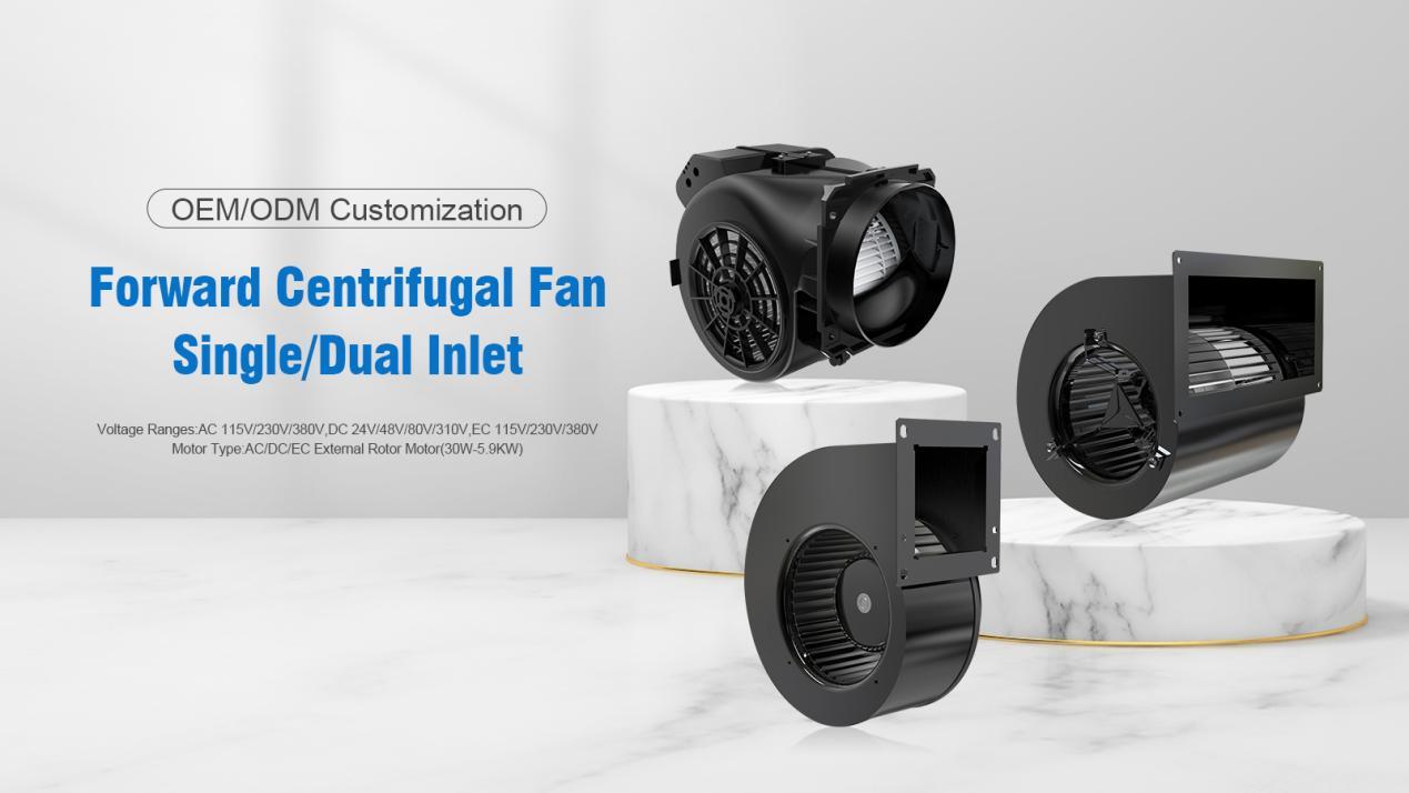
How Does a Forward-Curved Centrifugal Fan Work?
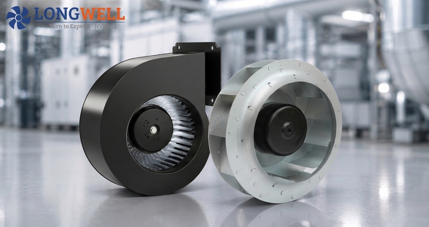
Like their backward-curved counterparts, forward-curved centrifugal fans derive their name from the specific path the air takes through the unit. Air is drawn in axially and discharged at a 90-degree angle. The defining engineering difference lies in the shallow design of the impeller blades, which thrusts the air tangentially from the impeller’s circumference, setting it apart from other blade profiles.

Visually, a forward-curved centrifugal fan is characterized by its cylindrical form factor, packed with numerous small blades around the impeller’s outer edge. In standard configurations, such as the example illustrated below, the fan is designed to rotate in a clockwise direction.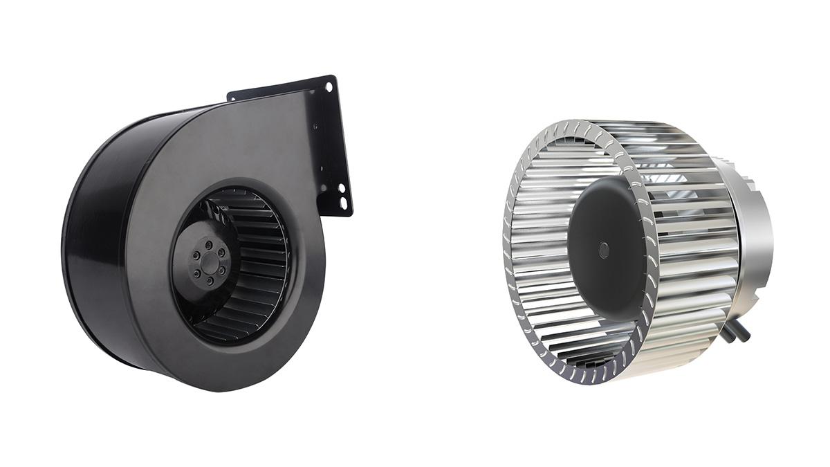
The Critical Role of the Scroll Housing
Unlike a backward-curved impeller, a forward-curved impeller relies entirely on a surrounding housing to function efficiently. This housing, commonly referred to as a scroll volute, plays a crucial aerodynamic role. It captures the high-velocity air exiting the blade tips and decelerates it, converting that kinetic energy into a lower-velocity, but significantly higher-pressure flow directed toward the exhaust outlet.
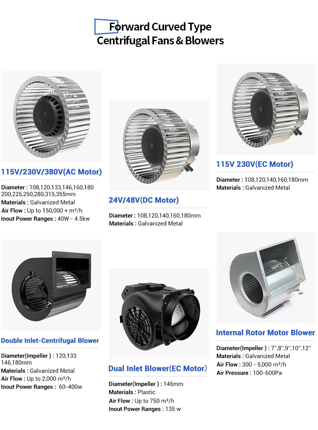
These blowers are typically manufactured in two primary configurations:
· Single Inlet: This design draws air from one side of the housing through a round inlet and pushes it out through a perpendicular outlet.
· Double Inlet: Engineered with a wider scroll housing, this variant draws air from both sides simultaneously to achieve higher volume flow rates within a compact footprint, discharging through a proportionately wider outlet.
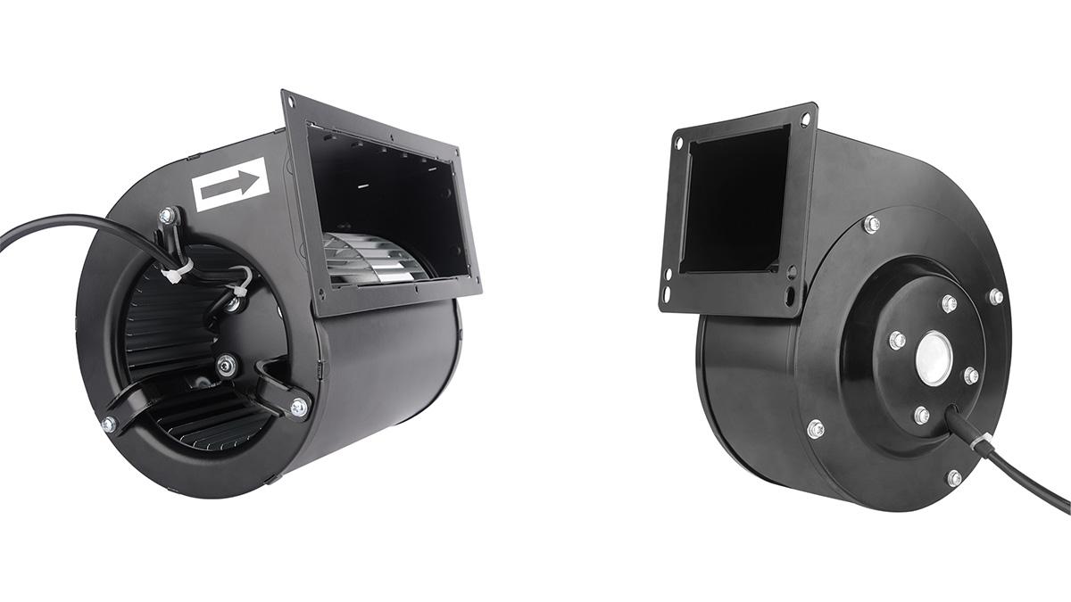
As seen below, the single inlet blower (left) directs air to a square outlet equipped with a mounting flange. The double inlet blower (right) utilizes its wider scroll to maximize intake and exhaust volume. Regardless of the inlet type, the suction side of the blade continuously draws air from the center, resulting in the signature 90° directional change between intake and exhaust.
Understanding the Performance Curve
Forward-curved centrifugal fans excel in applications that demand high pressure against relatively lower volume flows. The performance graph below illustrates their optimal working areas:
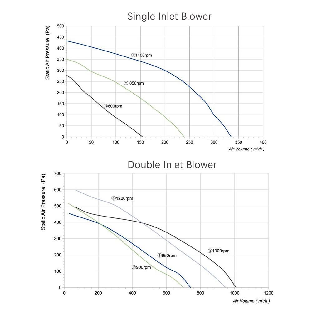
On these graphs, the X-axis plots the volume flow, while the Y-axis tracks system static pressure. When a system exerts zero pressure (free-blowing state), the forward-curved fan generates its absolute highest volume flow. Predictably, as resistance increases on either the suction or exhaust side, the volume flow rate drops.
⚠️ Engineering Caution: Avoid specifying a forward-curved blower for operations that require maximum volume flow at extremely low pressures. In these scenarios, the impeller falls into an aerodynamic stall—similar to an axial fan hitting the saddle point on its performance curve. This turbulence drastically spikes noise levels and power consumption.
Instead, target the “knee” of the characteristic curve. This peak efficiency point occurs when the ratio of output power (volume flow × static pressure) to electrical input reaches its maximum, yielding minimal sound pressure. Straying beyond this optimal operating range degrades system efficiency and increases acoustic output.
Application Benefits by Type:
· Single Inlet Impellers: Offer a exceptionally steep characteristic curve, making them ideal for systems requiring consistent particulate filtration. As finer filtration grades capture smaller particles, the filter gradually clogs, driving up system pressure. The steep curve ensures that the volume flow remains constant even as this filter pressure rises.
· Double Inlet Impellers: Capable of delivering impressive high-volume flow despite their relatively compact size. The trade-off is a sacrifice in pressure development, making them strictly suitable for lower-pressure systems.
Mounting Options and Clearances
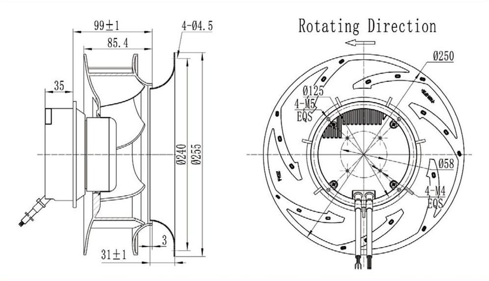
Because forward-curved impellers generate high-velocity air at the blade tips, the surrounding scroll housing must be meticulously proportioned—based on a specific ratio of distances from the impeller center to the fan outlet—to properly convert dynamic pressure into static pressure. Furthermore, to prevent internal air recirculation, it is highly recommended to engineer a slight overlap between the inlet ring and the mouth of the impeller. These structural considerations are detailed in the schematics below:
Mounting Options and Clearances
Because forward-curved impellers generate high-velocity air at the blade tips, the surrounding scroll housing must be meticulously proportioned—based on a specific ratio of distances from the impeller center to the fan outlet—to properly convert dynamic pressure into static pressure. Furthermore, to prevent internal air recirculation, it is highly recommended to engineer a slight overlap between the inlet ring and the mouth of the impeller. These structural considerations are detailed in the schematics below: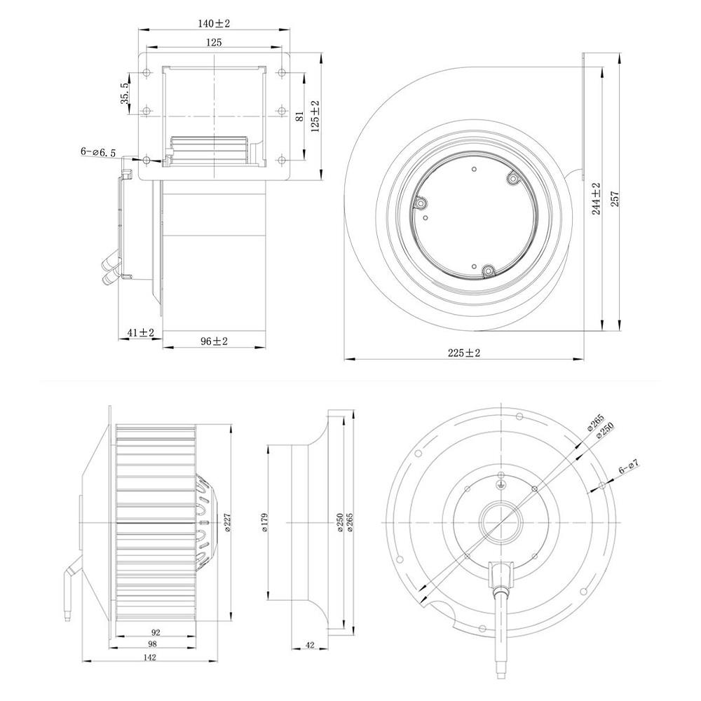
The diameter of the inlet ring should be precisely calculated to allow only a minimal gap between the impeller and the ring itself, strictly avoiding the recirculation of air.
Crucial Clearance Guidelines Maintaining adequate physical clearance on both the suction and exhaust sides of the blower is critical to operational success. Insufficient clearance on the suction side artificially elevates inlet velocity, which immediately induces air turbulence. As this turbulent air passes through the impeller, it disrupts the energy transfer from the blades to the air, driving up noise levels and severely diminishing overall efficiency.
General best practice for inlet conditions:
· Inlet Side: Strictly avoid placing any obstructions or causing alterations in flow direction within a distance equal to 1/3rd of the fan’s diameter from the air inlet.

Summary: Making the Right Choice
When should you specify a forward-curved centrifugal fan?
1. Choose Single Inlet if your required duty point falls within the higher system pressure and lower volume flow region of the performance curve.
2. Choose Double Inlet if your application demands a high-volume flow but must fit within tightly confined spatial constraints.
3. Target the “Knee” of the characteristic curve. Selecting a fan that operates within this optimal range (typically closer to the higher-pressure limit) ensures maximum aerodynamic efficiency and the quietest possible operation.
4. Avoid Extreme Margins: Operating outside the peak efficiency zone—particularly at extreme high-volume flows—invites destructive turbulence, aerodynamic stall, and excessive noise. In low-pressure/high-flow scenarios, always monitor the motor’s operating temperature under load to actively prevent overheating.
5. Optimize Airflow Path: Prioritize smooth, laminar airflow at the inlet by respecting the minimum 1/3rd impeller diameter clearance rule. Utilizing an overlapping inlet nozzle will effectively eliminate flow disturbances, cut turbulence-induced noise, and keep power consumption to an absolute minimum.
Thanks to the steep operating characteristics and high-pressure capabilities of single inlet models, paired with the high-flow potential of double inlet variants, forward-curved centrifugal fans stand out as a highly versatile, reliable option for a broad spectrum of HVACR and industrial installations.
Contact LONGWELL:
Website: www.longwellfans.com
Email: sales@zjlongwell.com