Please leave your email so that we can communicate with you further
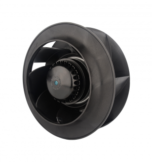
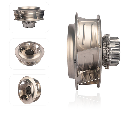
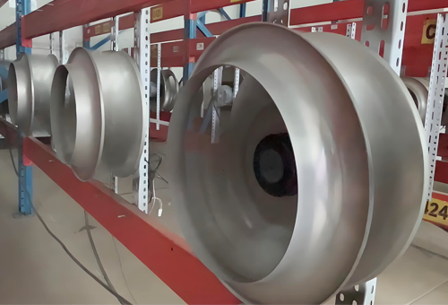
Backward Curved Centrifugal Fans
How many types of backward centrifugal fans does LONGWELL produce ?
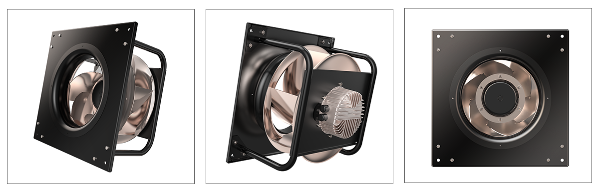
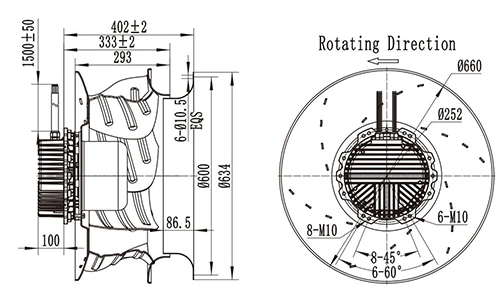
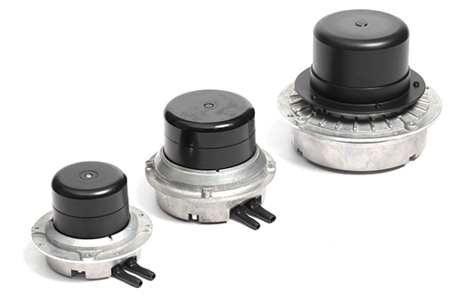
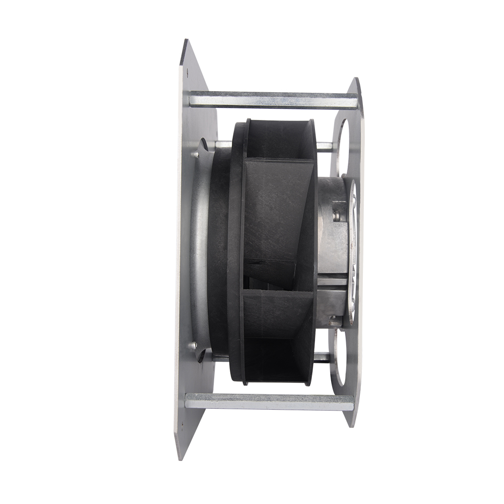
Type 1 : Standard backward centrifugal fan without bracket
Motorized impellers are available in sizes 133 to 630 in combination with all motor sizes up to motor size 218.
In addition to an inlet ring, an appropriately dimensioned motor mount must be provided on site to operate a motor-impeller.
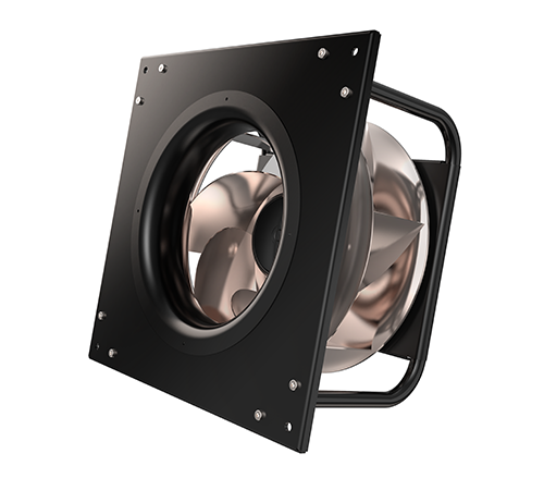
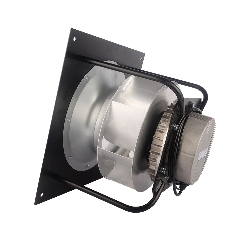
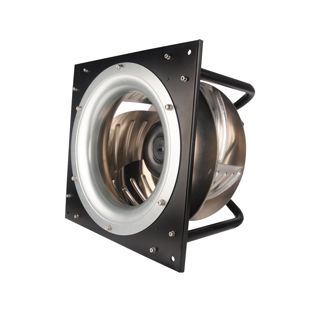
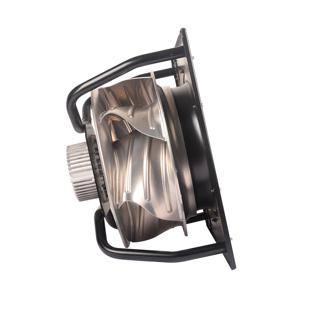
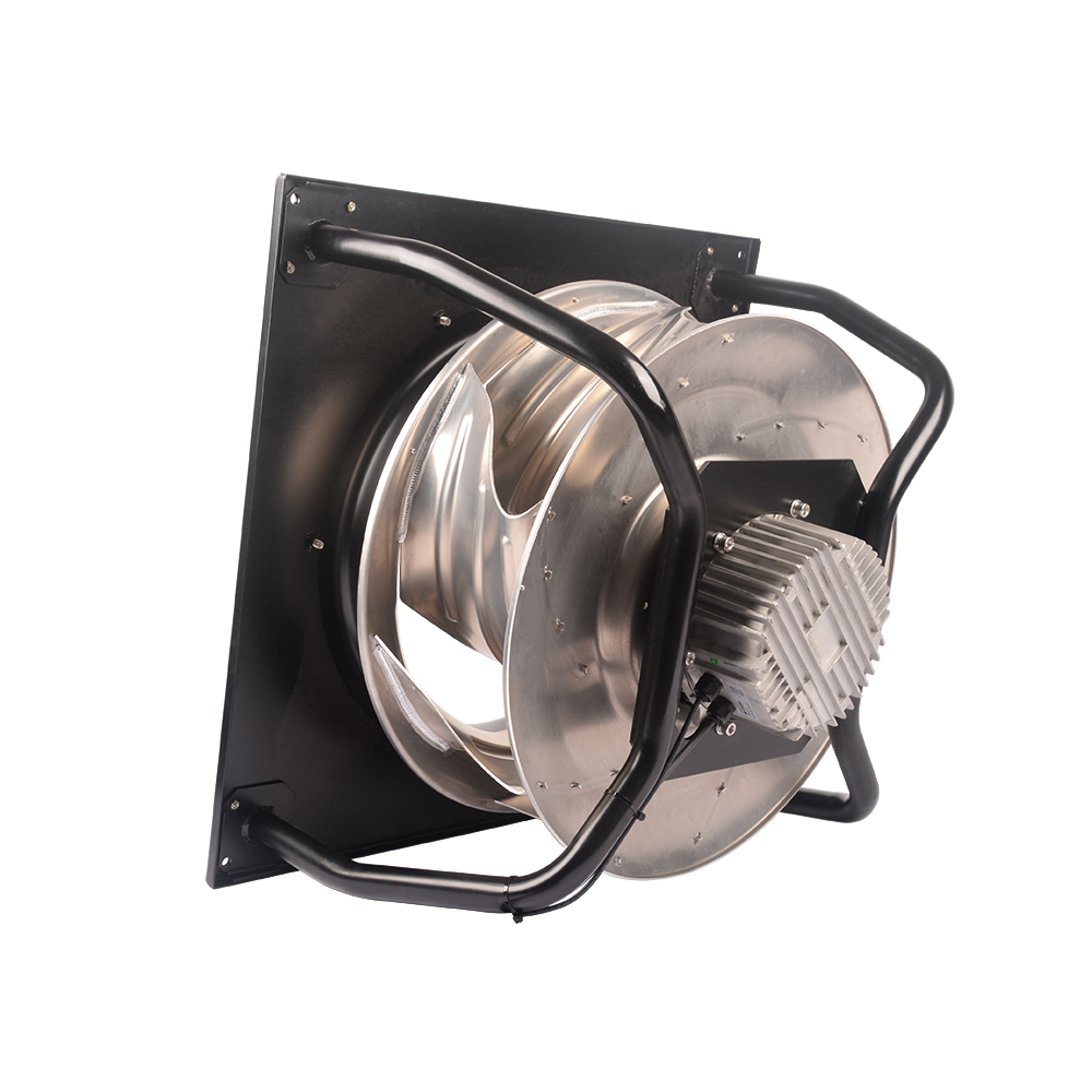
Type #2: Backward centrifugal fan with mounting bracket
LONGWELL Backward centrifugal fan with a support bracket are also available in sizes 250 to 560 in all impeller/motor combinations as ready-to-install support struts for wall mounting.The support bracket design includes the motor-impeller, a welded support strut design, an inlet ring and a square mounting plate.
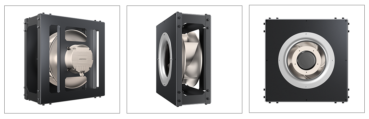
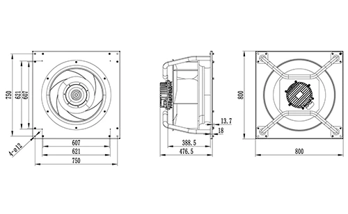
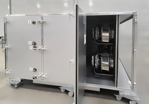
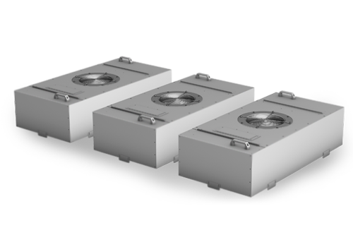
Type 3: EC PLENUM backward centrifugal fan
LONGWELL EC centrifugal fan with a cube design with impeller diameters 310 to 560mm and the large size 218 motor are only available in the cube design intended for floor mounting.The struts are extruded aluminum profiles, the corner joints are made of die-cast galvanized metal sheet, and the motor mounting plate, inlet ring and nozzle plate are made of galvanized sheet steel.Bye the way ,this version is not suitable for wall mounting
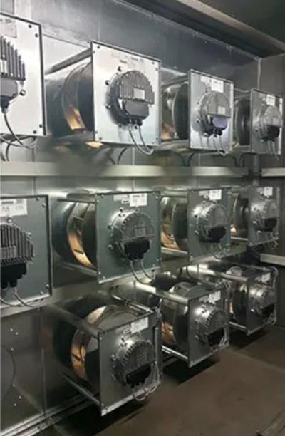
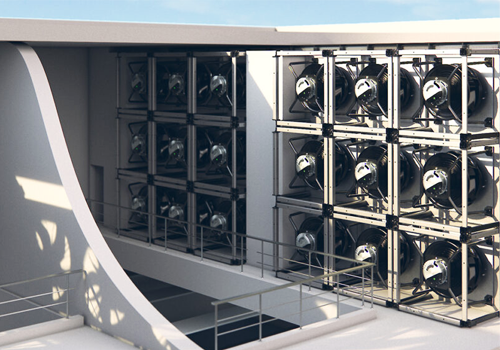
Type 4: EC Fan Grid
FanGrid modules are made of few quantities of LONGWELL EC centrifugal fans with a support bracket in a special cube design.The pre-assembled units in sizes 355 to 560 were designed for setting up the FanGrid .They are suitable for applications with very high volumes of air that cannot be achieved by a single fan with the required compact design.
EC centrifugal fans with high static pressure
Ventilating large buildings efficiently – with ready-to-install EC Plug fans .
Main Features of EC Fans :
• Sensorless permanent magnet motor drive;
• Wide input voltage range, single-phase 110-270V, three-phase 250V-480V, 50/60Hz;
• PFC(Power factor correction): Passive and active(IEC61000-3-2);
• Soft start, adjustable acceleration, CVT;
• Design operating temperature range: -25 – 60 degrees of minimum selection (The device in accordance with -40~ 85 degrees);
• Protection: Overvoltage, undervoltage, overtemperature, overcurrent, phase loss detection, communication failures….
• The basic interface: 0-10V/PWM, RS485/Modbus, 4-20mA…
• The basic parameters of field-programmable: Maximum speed, minimum speed, maximum power, maximum current, resonance avoid….
• Constant air pressure controlling function;
• Embedded Design;
• EMC(Electro Magnetic Compatibility).
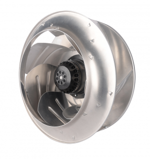
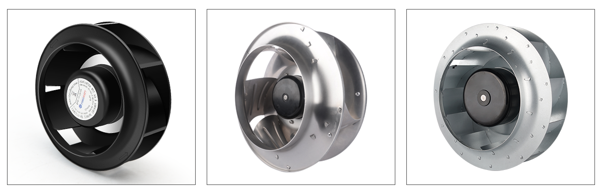
Three kinds of Structure of EC Backward centrifugal fan and plenum fan :
Test stand design and tests in accordance with ISO 5801 – Industrial fans, performance measurement on standardized test stands DIN EN ISO 3744, DIN EN ISO 3745, ISO 13347-3 – Acoustics standards Measurement quantities and measurement accuracies attained with the aero-acoustic test stand.
EC Fan specific structure and characteristics:
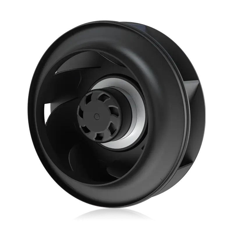
High-performance impeller
High static efficiency :
– Aerodynamically optimized blade channel
– Integrated radial diffuser
– Inlet ring tuned to impeller
Low noise emission :
– Diagonal trailing edge for optimal flow control
– Integrated radial diffuser
Minimal vibration :
– Dynamic balancing of impeller rotor unit minimizes induced structure-borne noise and reduces bearing load
– Minimum residual imbalance thanks to complete balancing, meaning balancing only takes place after installation of all rotating parts (guaranteeing extremely smooth operation)
Rugged design:
– Suitable for constantly high peripheral speeds
– Corrosion-resistant aluminum
GreenTech EC motor
Unbeatably compact :
– The impeller is mounted directly on the rotor of the motor
High efficiency :
– Low copper and iron losses
– Synchronous running prevents slip losses
– Use of permanent magnets prevents magnetic hysteresis losses in the rotor
Economical operation :
– Optimized commutation enables partial-load operation down to 1:10 with sustained high efficiency
Low-noise emission :
– Commutation and stator design ensure low-noise magnetization of main field
– High, acoustically imperceptible cycle frequency
Long service life :
– Maintenance-free bearings
– Brushless commutation
– Insulated bearing system to prevent bearing currents
High-performance impeller
Support bracket Easy installation in AHU
– Complete system for quick and easy installation
– Nozzle plate for easy attachment of fan to equipment wall
– Installation with horizontal OR vertical motor shaft
– Compactness enables new design flexibility Aerodynamically perfected
– Aerodynamically efficient
– Optimized factory positioning of nozzle
Electronics and connection
Adaptable :
– Infinitely variable speed adjustment
– Control signal 0–10V DC / PWM and MODBUS
Universally deployable :
– Wide voltage range 110V,230V,400V
– Suitable for use with 50 and 60 Hz networks
Safe operation :
– Integrated locked-rotor and thermal overload protection
– Environment-resistant cable glands
Simple commissioning :
– Central terminal area for supply connection, alarm relay, as well as control and communication
– Safe separation of terminal area and electronics
– No adjustment required
Efficiency Calculations examples
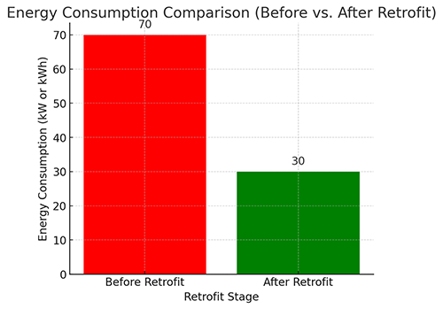
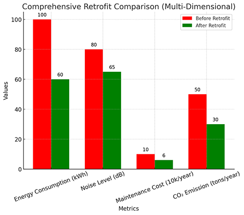
Reduces energy costs by an average of 50% and reduces CO2 while protecting environment.
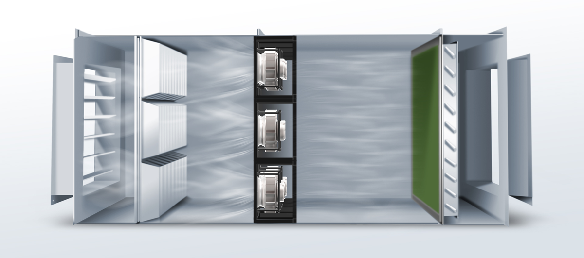
An ECFanGrid consists of an array of EC fans operating in parallel. The flow rate is multiplied proportionally to the number of fans, while the pressure conditions remain constant. Highly efficient EC fans are the perfect combination of motor, electronics and turbine.They allow simple plug & play solutions for any ventilation need.
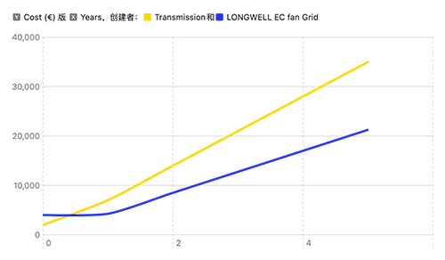
By replacing old, inefficient fans with high-efficiency EC fans, we can save around 50% energy and CO2. By relatively low investment costs (about 3% of the air conditioning system cost), we can reduce the operating cost of the system by up to 70%. The investment is recovered over a period of 2 to 5 years on average.
ECFanGrid offers an enormous degree of reliability thanks to its redundancy. In the unlikely event of a fan failure, the remaining fans automatically increase speed to compensate for the loss of airflow.The combination of fans allows the unit to adapt much better to any duty point.
Cost comparison
Energy Consumption Comparison (Before vs. After Retrofit)
What is the main applicaiton for this EC Motor centrifugal fan ?
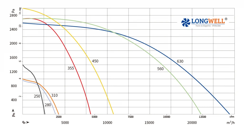
As the characteristics of high air volume and wide coverage of static pressure in the field of ventilation, EC rear tilt centrifugal fans are widely used in HVAC, refrigeration, heating, ventilation equipment, purifiers, clean rooms, FFU, AHU, precision air conditioning and other applications, the highest air volume up to 24000m³/h, the highest static pressure up to 3270Pa. It is highly customizable and can be customized according to the actual working conditions of customers
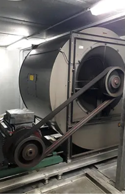
AHU Refurbishment
With a maximum static pressure of 2300 Pa, the fan satisfies the high-resistance demands of AHU applications. A single fan can deliver up to 6 kW of power and a maximum airflow of 23,000 m³/h. Additionally, for industrial applications, a fan wall combination option is available, providing flexible solutions to meet diverse application requirements.
The energy loss, high maintenance costs, and potential stability issues associated with traditional belt-driven fans in AHUs can be effectively addressed through our fan wall retrofit solution. Compared to conventional forward belt-driven fans, the upgraded fan wall can improve efficiency by 20% to 50%.
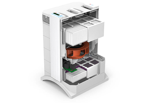
Air Purifier
Backward-curved centrifugal fans are revolutionizing air purification in residential and commercial settings, delivering unmatched efficiency, quiet operation, and reliability. Designed for optimal air circulation and filtration, these fans excel in air purifiers by leveraging their aerodynamic design—curved blades that minimize turbulence, reduce energy consumption, and maximize air volume under high static pressure (ideal for dense filter media).High-Efficiency Airflow: Generate consistent, high-volume airflow (up to 500+ CFM) while maintaining energy efficiency (10–30% less power than traditional fans), ensuring rapid air turnover for HEPA/activated carbon filters.
Commercial & Industrial Ventilation
As the demands for commercial and industrial environments increase, the performance requirements for HVAC equipment have become more stringent. Our fans must be able to achieve precise control of temperature and humidity with 100% accuracy. Additionally, there is growing concern about fan energy consumption, maintenance costs, and noise pollution.
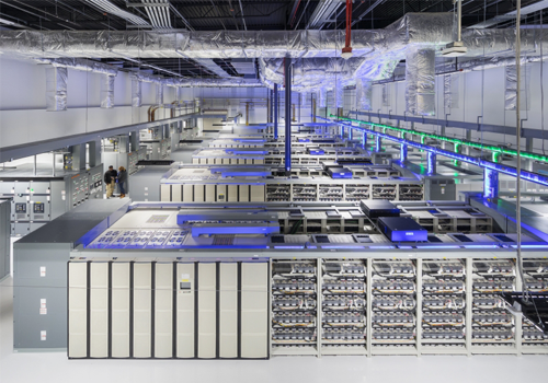
Data Center
To meet the airflow and efficiency requirements of data centers, a 630 medium static pressure high-efficiency fan series has been specifically developed. This series is designed to provide optimal performance, balancing airflow demands with energy efficiency, making it ideal for data center applications.
FFU (Fan Filter Unit)
For FFU (Fan Filter Unit) applications, which require high efficiency, low noise, and stable group control in medium to low static pressure environments, two highly efficient fan models, have been specifically developed.
These models are tailored to meet the unique demands of FFU systems, ensuring optimal performance in such scenarios.
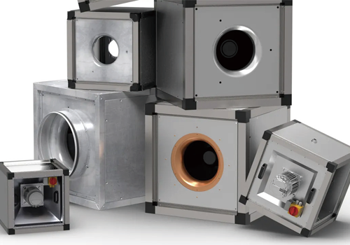
Fan Wall Combination
Impeller sizes ranging from 310 to 630mm are available to fit different installation spaces, and standard mounting brackets can be selected
for quick and convenient installation.Can be combined into a fan wall to achieve greater airflow.EC/DC/AC motors can be selected to match different equipment power requirements.Customizable to meet specific application needs, such as C5 corrosion protection, IP56 protection rating, and operation at temperatures as low as -30°C.
How to keep the Centrifugal fan work well in AHU ,FFU and other HVAC equipments ?
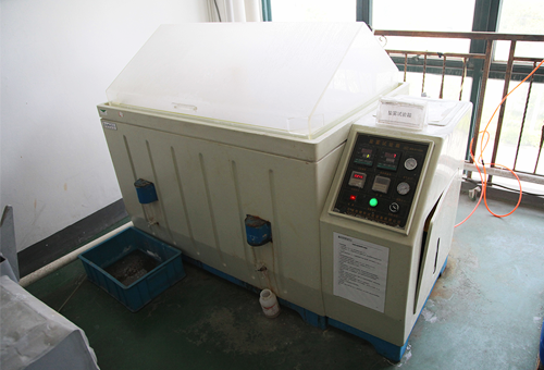
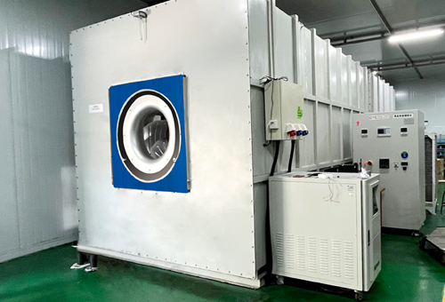
Salt Mist Test
Salt mist test assesses the corrosion resistance of the LONGWELL fan, especially under C5-grade corrosion conditions. It ensures long-term performance in salty environments, providing protective measures for aluminum-magnesium alloy impellers against corrosion.
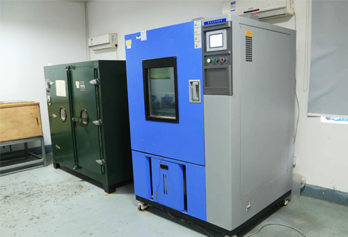
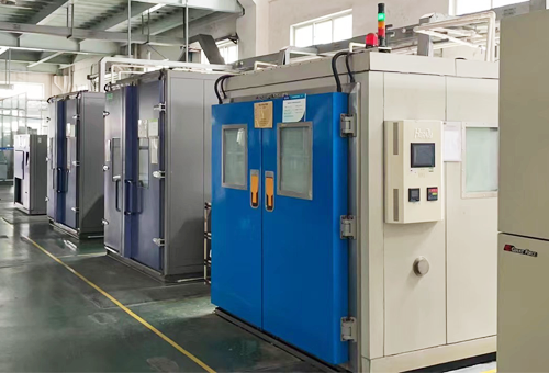
Temperature Shock Test
This test evaluates the operational stability of the fan under rapid temperature changes. The high-temperature materials and precise control system of the LONGWELL fan ensure that performance is not affected by thermal expansion and contraction under extreme temperature variations.
Salt Mist Test
This test measures the airflow output and fan efficiency under different speeds
and static pressure resistance. The optimized impeller design and threedimensional blade structure of the LONGWELL fan ensure efficient airflow output and adaptability to various working conditions.
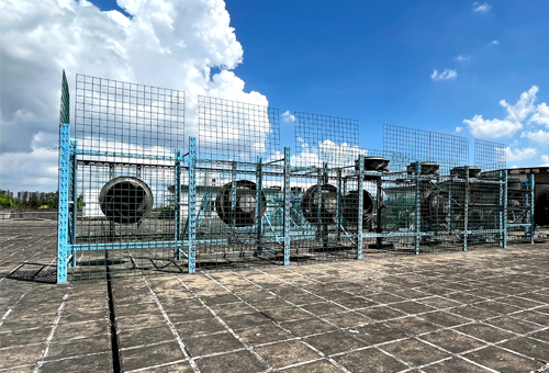
Outdoor Lifespan Test
This test validates the fan’s durability in harsh outdoor environments. The
LONGWELL fan’s IP55/IP56 protection rating, along with its high-temperature
and corrosion-resistant design, ensures reliable long-term operation
outdoors.
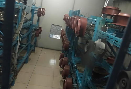
Indoor Lifespan Test
This test evaluates the long-term lifespan of the fan in standard indoor environments, ensuring that the LONGWELL fan has a long life with low maintenance requirements. The test is particularly focused on its performance in common applications such as AHU and FFU systems.
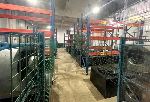
High Temperature Test
This test validates the reliable operation of the LONGWELL fan in hightemperature environments, especially under high static pressure and efficient electromagnetic design conditions. It ensures the stability of the impeller material at extreme temperatures, extending the fan’s lifespan.
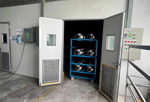
ConstantTemperature
& Humidity Test
This test validates the fan’s performance stability in environments with varying temperature and humidity, particularly in corrosion and moisture-resistant conditions. A 21-day continuous operation at 75°C and 95% humidity is used to verify the fan’s long-term stability
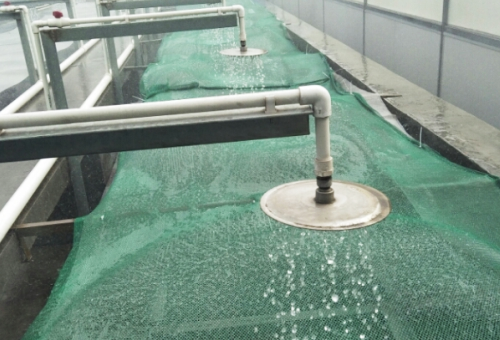
Spray test
The Water Droplet Spray Test is a critical evaluation for ventilation fans, designed to simulate operational exposure to moisture-laden environments (e.g., humidity, light rain, or condensation). This test ensures fan components—including motors, bearings, electrical systems, and structural materials—maintain corrosion resistance, electrical integrity, and functional reliability under prolonged moisture contact.
Aging test
The Aging Test evaluates ventilation fans’ long-term durability and reliability by simulating extended operational cycles and environmental stresses (e.g., temperature fluctuations, humidity, vibration, and dust). This accelerated assessment ensures fans maintain structural integrity, performance efficiency, and safety compliance throughout their designed lifecycle.
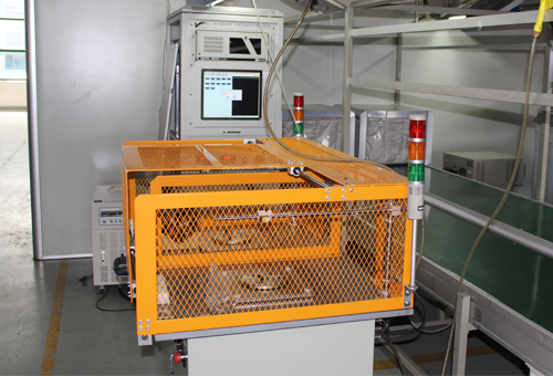
Runout testing
The Runout Test is a critical quality control procedure for centrifugal fans, measuring rotational alignment (radial/axial runout) of impellers, shafts, and bearings. By quantifying deviations from perfect concentricity, this test ensures fans operate with minimal vibration, noise, and mechanical stress—key to optimizing performance, durability, and safety.
High-Speed Lifespan Test
This test focuses on verifying the strength and stability of the LONGWELL fan’s impeller under long-term high-speed operation and ensures that the impeller remains free from deformation or damage under highspeed conditions, ensuring the fan’s safety and reliability, especially in applications requiring high-efficiency airflow output.
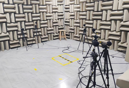
Noise Test (BK Noise ROOM)
This test verifies the low noise performance of the fan at high speeds and high static pressure, analyzing noise through FFT noise spectrum analysis.
The optimized flow path and blade design effectively reduce noise levels, improving the overall comfort of the operating environment. It minimizes the transmission of low-frequency noise over long distances in ventilation ducts.
FAQ Summary from Engineer and Customer
How to choose a suitable fan or blower for AHU,FFU or other ventilation equipments ?
When selecting a fan for a specific application, these parameters play an important role:
– Air flow with given back pressure – Voltage supply, divided into DC and AC voltage (1~, 3~) – Noise generation – Efficiency – Available mounting space
What is the operating conditioning requirements for the EC backward centrifugal fan ?
or Customized ,contact our engineer team by sales@longwellfans.com .
What is the electronic protection function included in this backward centrifugal fan ?
Electronic / Thermal protection for this product
EC motor : Control input 0-10VDC/PWM, Tech output, Locked-Rotor
protection, Reverse Polarity, Over-voltage protection, Soft Start Protection(Delay time <35 seconds to full speed)
Information on motor protection and thermal protection is provided in product-specific data sheets.
The following protection methods are provided depending on the type of motor and area of application:
– Thermal overload protector, in-circuit or external ;
– PTC with electronic diagnostics;
– Impedance protection ;
– Thermal overload protector with electronic diagnostics ;
– Current limitation via electronics ; If use is made of an external thermal overload protector, a commercially available tripping unit must be connected by the customer for shut-off. Motor protection conforming to the applicable standard must be fitted for products not provided with a built-in thermal overload protector and not protected against improper use.
How long does this motor can operated ?
Lifespan of this product :40,000 hours (EC MOTOR with ball bearings) , 30,000 hours (AC MOTOR with ball bearings)
The service life of the bearing system is primarily governed by the thermal load on the bearings. For the majority of our products, we use maintenance-free ball bearings which can be fitted in any installation position. Sleeve bearings can alternatively be employed, as described in product-specific data sheets.
As a rough guide (depending on the general conditions), the ball bearings have a life expectancy L10 of approx. 40,000 hours of operation at an ambient temperature of 40 °C. We will gladly provide you with a life expectancy calculation based on your specific usage conditions.
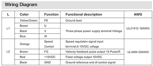
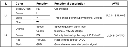
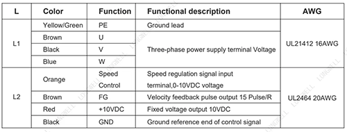
What is the electronic wire diagram for this centrifugal fan ?
Fan connection modes vary according to different voltages and operating conditions (such as speed regulation requirements). Draw a connection diagram based on the fan configuration in use. The following shows two common EC centrifugal fan motor connection modes for reference only. Specific project requirements can be connected with our company’s sales engineers
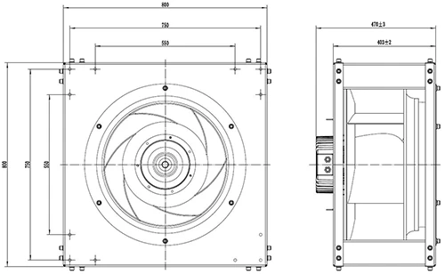
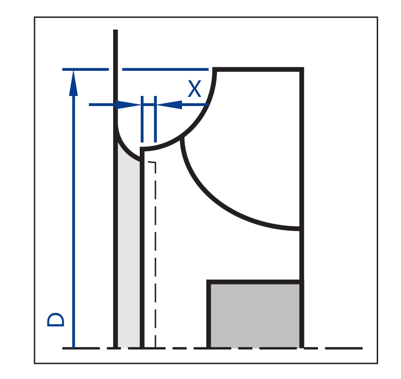
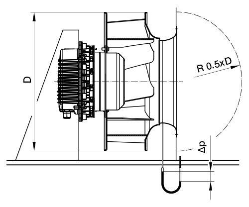
What are the effects of the nozzle (air inlet ring ) gap dimension on the equipment?
The centrifugal air gap between the inlet nozzle and impeller cover plateinfluences the air performance and efficiency of the centrifugal fan.
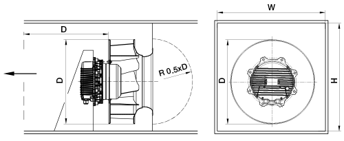
What is the effects of installation space for the EC Plenum fan when mounted in an AHU ?
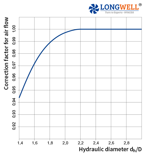
Effects of installation spaceWhen mounting our product in a rectangular box, air performancemight be reduced.
dh= Hydraulic diameter Formula: dh=2xB xH/(B + H) B= Width of box H= Height of box D= Outer diameter of the fan Airflow determination for inlet rings with pressuretap: The differential pressure method compares the static pressureupstream ofthe inlet ring with the static pressure in the inlet ringThe airfow can be calculated from the differential pressure (bet.ween the static pressures) according to the following equation: