In-Depth Guide: Standard Installation Process, Commissioning Specifications, and On-Site Troubleshooting for Cross-Flow Fans
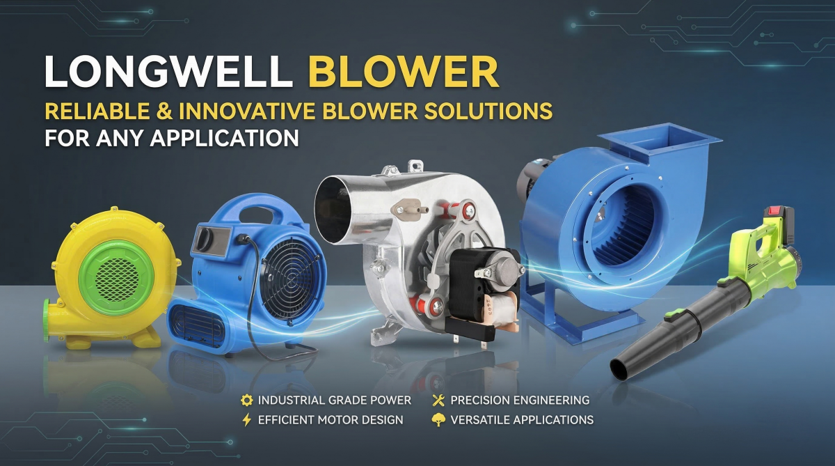
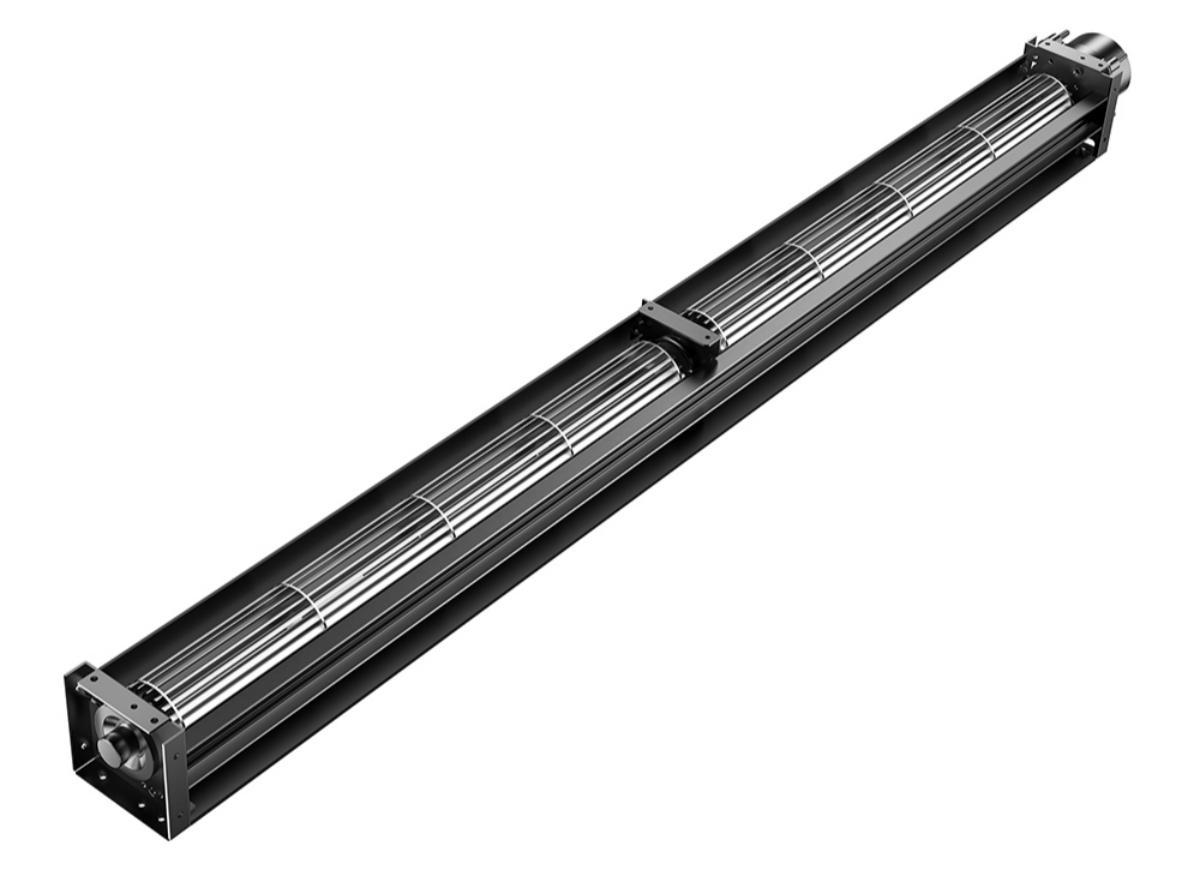
In modern ventilation and environmental control engineering, the rationality of airflow organization directly determines the success or failure of the entire system. Cross-flow fans, also commonly known as tangential fans in the industry, are core dynamic equipment that changes the direction of airflow and reshapes the spatial airflow field. Essentially, a cross-flow fan is a fluid machine capable of guiding air from one direction and delivering it uniformly to another. Relying on their unique long cylindrical structure and excellent “air curtain” wide-angle air supply capabilities, they are widely used in industrial workshop ventilation, large commercial complex air conditioning terminals, as well as heat dissipation and climate control systems for various precision equipment.
There is an unbreakable truth in the electromechanical installation industry: “30% equipment, 70% installation.”
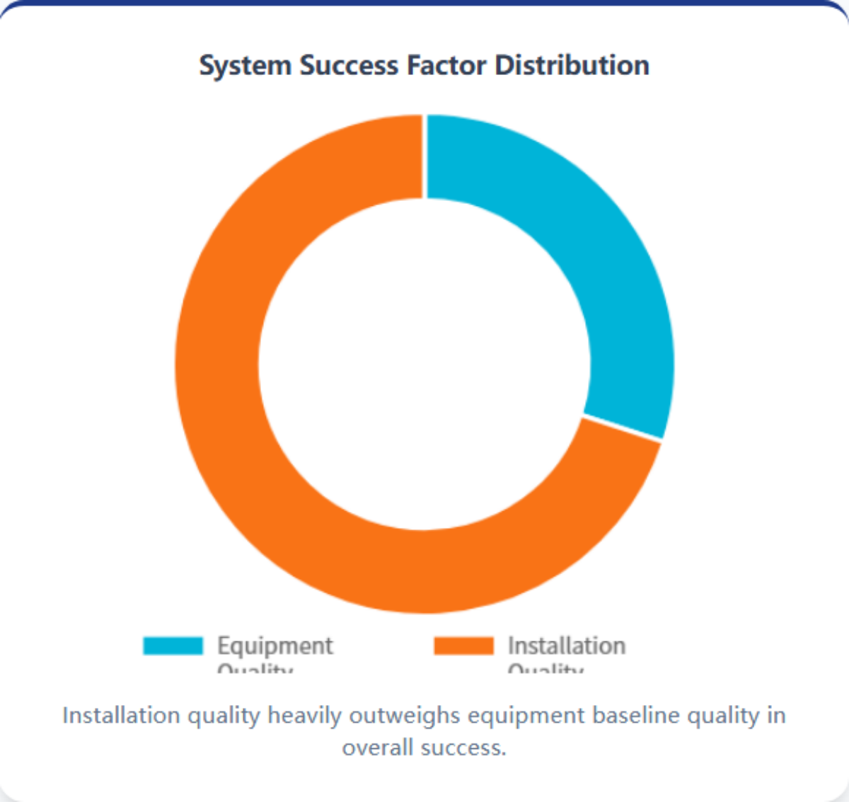
Even for high-quality fans like LONGWELL, which achieve ultimate impeller dynamic balance before leaving the factory, if the construction phase is botched, they will absolutely fail to exert their due aerodynamic performance and may even trigger severe noise and lifespan reduction issues. Generally speaking, although the installation logic of a cross-flow fan is not complicated, strictly following standard SOPs (Standard Operating Procedures) is an insurmountable bottom line to ensure the equipment operates safely, efficiently, and for a long cycle.
To enable every construction worker, maintenance technician, or even hardcore equipment modification enthusiast to get the installation right the first time, this article will comprehensively deconstruct the standard construction process of cross-flow fans, from equipment cognition and site surveying to live testing.
Core Component Cognition: “Anatomy” Before Construction
Before picking up a drill and multimeter, we must first understand the equipment in our hands. Combining the structural characteristics of the fan, a high-standard cross-flow fan usually consists of the following core modules. Understanding them can help us avoid violently destroying key structures during construction:
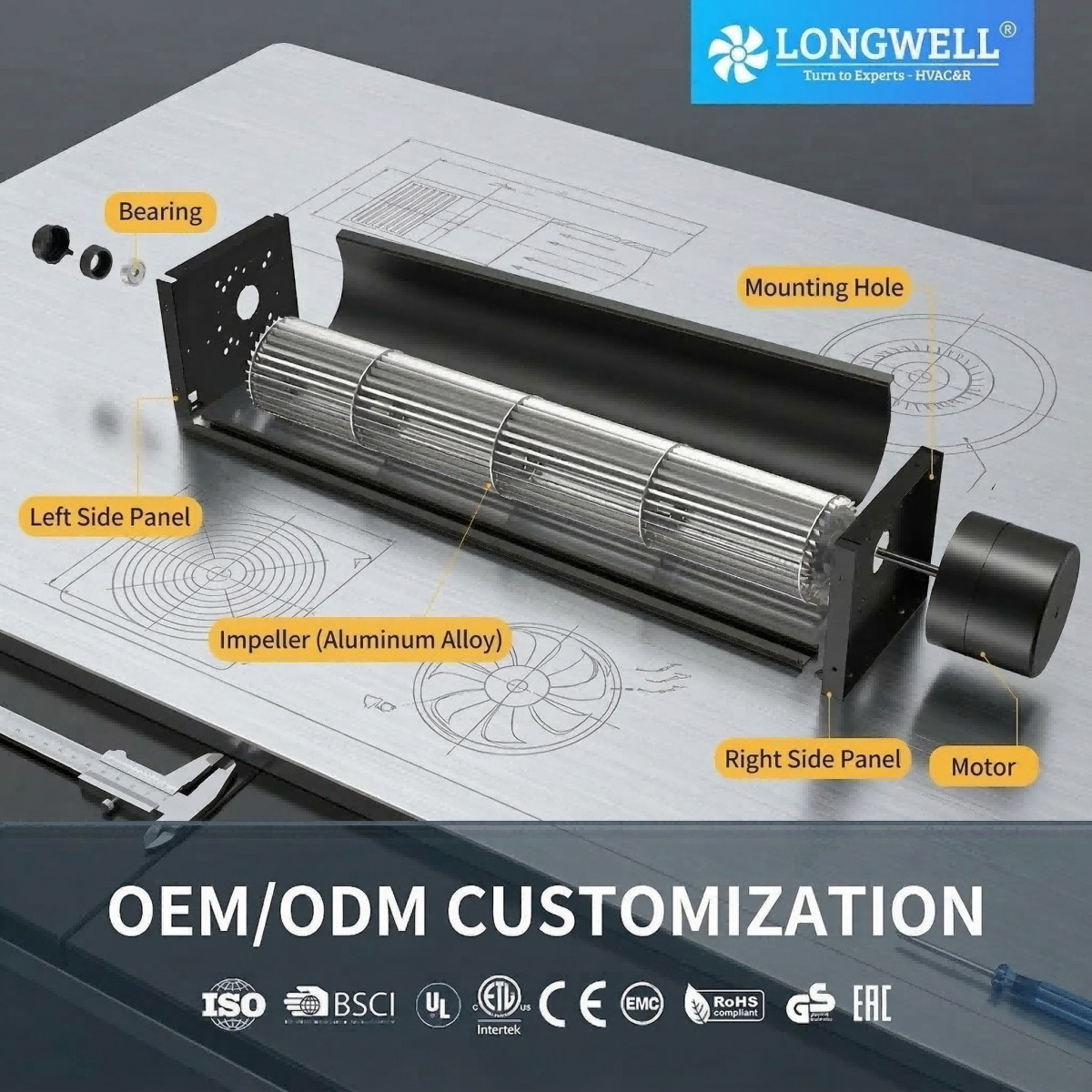
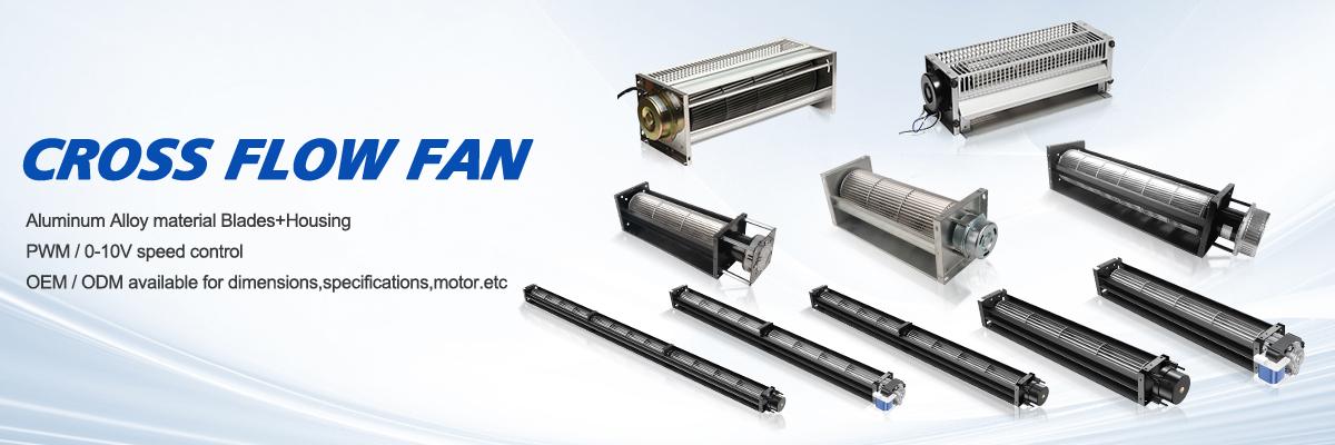
- Aluminum Alloy Cross-Flow Impeller: This is the “heart” of the fan. The multi-blade, long-wheelbase design allows it to cut air transversely, providing a uniform and broad air band. High-strength aluminum alloy is used to reduce dead weight while ensuring strength, which is crucial for maintaining dynamic balance during high-speed rotation.
- Drive Motor System: As the power source, it is usually seamlessly docked on one side of the equipment. The motor’s torque and speed directly determine the fan’s air volume and air pressure performance.
- Left and Right Baffle Side Panels: Not only do they support the overall framework and secure the motor and bearings, but they are also key components for internal airflow guidance. Their volute curvature is strictly calculated based on aerodynamics.
- Air Outlet and Air Inlet: The air pressurized by the impeller is finally blown out at high speed in a band shape from the air outlet, while a broad air inlet is the prerequisite for ensuring smooth “breathing.”
- Mounting Positioning Holes: Usually reserved on flanges or side panels, these are the anchor points connecting the equipment to the physical building structure.
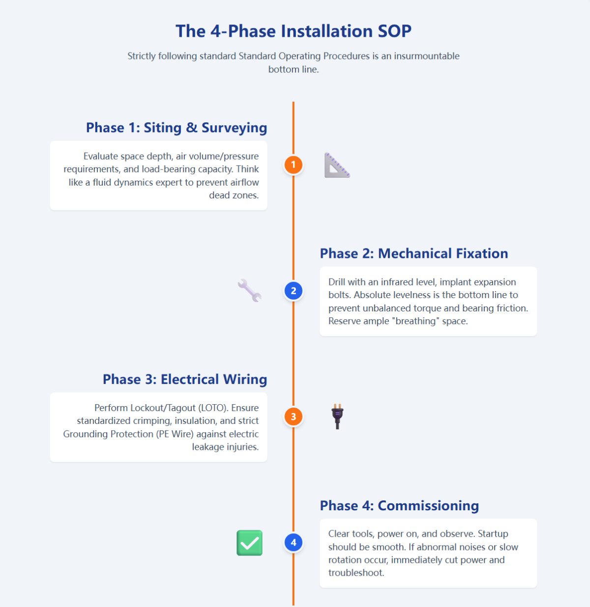
Construction Phase 1: Scientific Siting and Airflow Field Surveying
Many novices like to “stick it wherever it fits” when installing fans, installing it wherever there is an empty space. This is an extremely amateur practice in engineering design. The first step in installing a cross-flow fan, and also the step that tests engineering literacy the most, is choosing the correct working position.
The fan must be arranged in an area where the system genuinely needs ventilation and can exert its maximum efficiency without interference. Before finalizing the point, the construction manager needs to think like a fluid dynamics expert, comprehensively surveying and evaluating the following three core physical elements on-site:
- Space Depth and Coverage Radius: Evaluate the aspect ratio and floor height of the room, which directly determines how far the fan needs to send air and whether airflow dead zones will form.
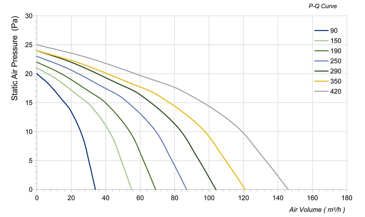
- Air Volume and Air Pressure Requirements: Clarify whether the site needs large air volume for overall ventilation or high air pressure to penetrate dense equipment grids. This determines the installation angle and height of the fan.
- Load-Bearing and Resonance Assessment: The load-bearing capacity of the wall, steel structure, or suspended ceiling must be far greater than the static dead weight of the equipment. More importantly, the dynamic load during the fan’s operation must be considered. If the installation surface is flimsy, it is highly prone to producing low-frequency resonance noise.
Construction Phase 2: Mechanical Fixation and Shock Absorption Treatment
After confirming the equipment location, the next step is the hardcore construction operation. We need to make adequate mechanical preparations for the safe settling of the fan.
Usually, precise drilling using an infrared level is required on load-bearing walls or steel frames, followed by implanting high-strength expansion bolts or arranging dedicated shock-absorbing mounting brackets to ensure the fan can be dead-locked onto the working surface.
The Bottom Line of Absolute Levelness
The impeller of a cross-flow fan is usually slender. If the installation is not level, the rotor will generate an unbalanced torque during high-speed rotation. This will not only subject the bearings to uneven friction, causing the howling sound to increase exponentially, but also accelerate mechanical wear, directly halving the equipment’s lifespan.
Reserving Ample “Breathing” Space
When securing the fan, be sure to reserve ample space on its air inlet side. Air needs to flow in freely without obstruction. If the air inlet is too close to the wall or blocked by obstacles, it will cause the fan to be unable to “inhale”. At this time, the impeller will idle under negative pressure. While the air output plummets, the motor will also overheat and burn out due to abnormal resistance.
Construction Phase 3: Electrical Engineering and Standardized Wiring
After the mechanical fixation is completed and passes inspection, the next step is the electrical connection phase that gives the equipment power. Before performing any strong current operations, the primary industry iron rule is: Be sure to cut off the upstream main power supply, verify the voltage, and perform Lockout/Tagout (LOTO)!
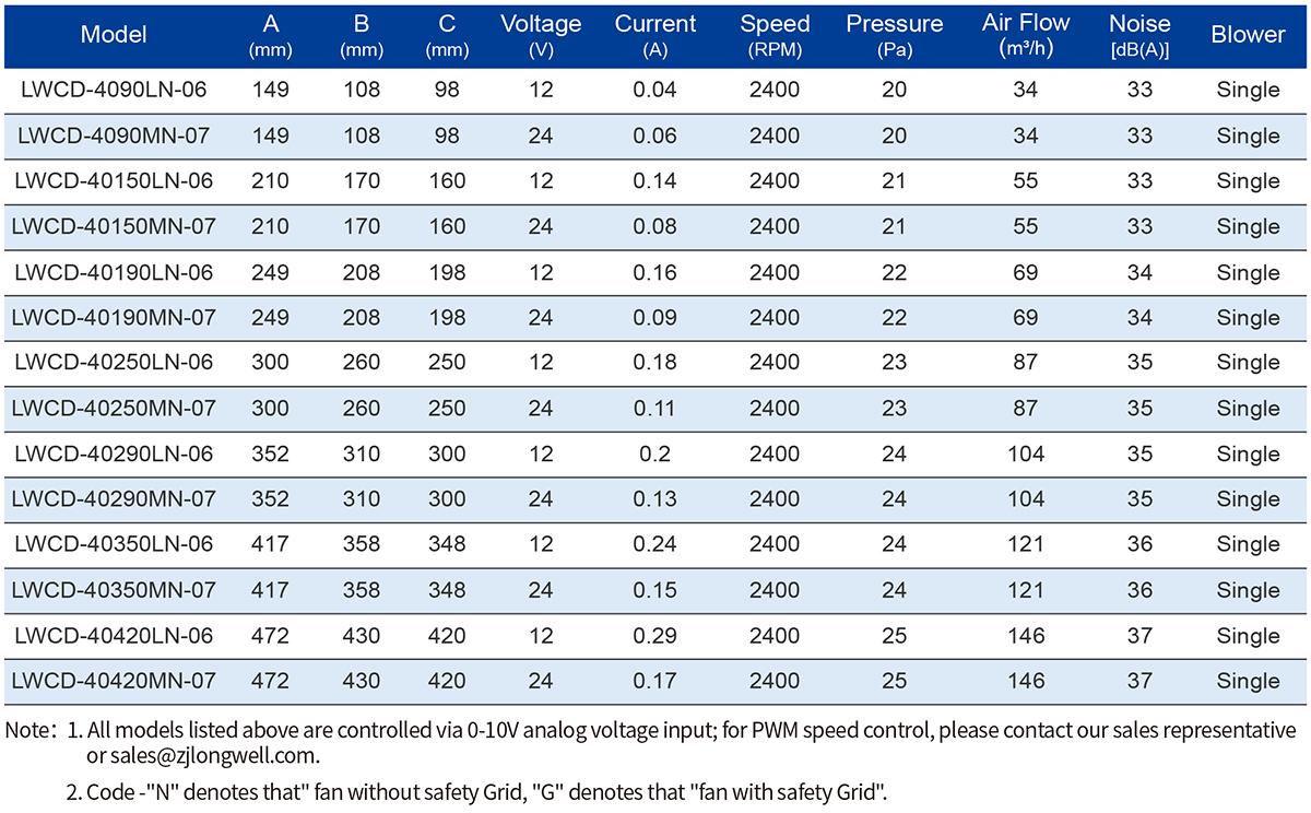
Cross-flow fans are driven by electrical energy and must be connected to a stable, matching power supply to operate normally. When stripping and wiring, strictly verify the voltage parameters (e.g., single-phase 220V or three-phase 380V) and frequency requirements on the motor nameplate.
Standardized Crimping and Insulation
Power cables cannot be simply twisted together; cold-pressed terminals or wire nuts must be used for standardized crimping. If the environment is damp, heat-shrinkable tubing is required for secondary insulation protection.
Series Connection of Control Circuits
Depending on the specific project design, the power cable may need to be connected to the fan’s own terminal block, or to external smart control nodes such as a variable frequency control box or thermostat panel.
Grounding Protection (PE Wire)
Fans with metal casings must be strictly connected to the ground wire. This is the last line of defense against electric leakage injuries and protecting the lives of on-site personnel.
Construction Phase 4: Live Testing and System Commissioning
With hardware and electricity all in place, it’s finally time for the system commissioning phase to test the results. Clear the site of tools, evacuate personnel from the fan’s direct blowing area, and prepare to power on.
Close the distribution box switch, turn on the power control switch, carefully observe, and ensure all fan functions are operating normally. An excellent cross-flow fan should start up smoothly and powerfully, with pure wind sound and no metallic friction noise.
Troubleshooting Principles
If the equipment does not rotate, rotates extremely slowly, or emits ear-piercing abnormal noises after being powered on, never let it continue to run forcefully. You should immediately cut off the power and shut down, re-examine issues like phase loss, loose wiring, or mechanical jamming, and completely eliminate the fault before conducting a secondary test run.
If the airflow is smooth, the fuselage has no obvious vibration, and the motor has no abnormal temperature rise after half an hour of operation, then the acceptance is passed, and you can prepare to fully enjoy the excellent environmental improvement brought by this new equipment.
Industry Senior Experts’ “Troubleshooting and Maintenance” Memo
In countless project repairs and after-sales on-site reviews, engineers have found that over 80% of premature equipment scrappage stems from carelessness during the initial installation and brutal usage later on. To protect your equipment investment, please be sure to bypass these common minefields:
Absolute Construction Taboos That Cannot Be Violated
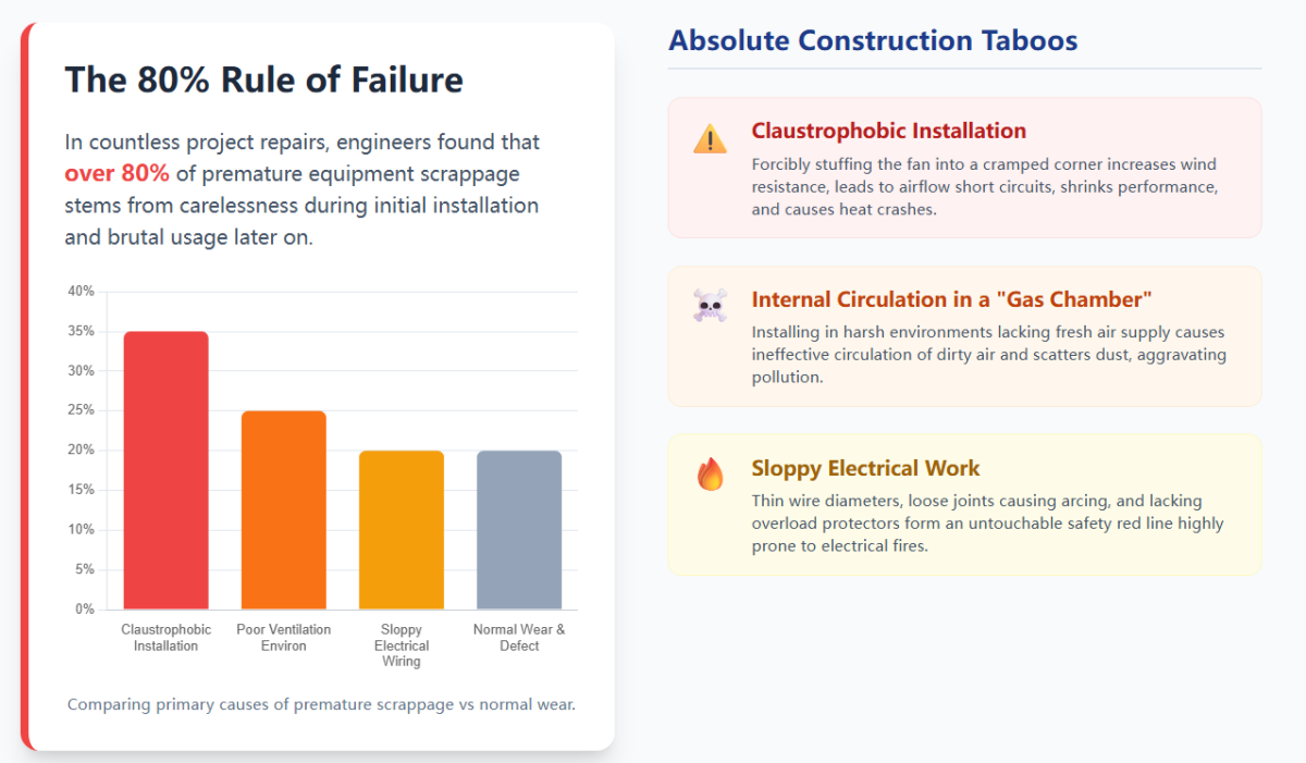
- Claustrophobic Installation (Confined Space): Forcibly stuffing the fan into an extremely small, cramped enclosed ceiling or corner is an absolute engineering taboo. This will greatly increase the system’s wind resistance, leading to airflow short circuits (the blown-out air is immediately sucked back in), which not only drastically shrinks performance but also causes the equipment to crash because heat cannot be dissipated.
- Internal Circulation in a “Gas Chamber” (Poor Ventilation): If the equipment is installed in an enclosed, harsh environment that inherently lacks a fresh air supply, it can only perform ineffective internal circulation of dirty air, and may even scatter dust from one place to the entire workshop, aggravating environmental pollution.
- Sloppy Electrical Work (Wiring Errors): Selecting wire diameters that are too thin causing wires to heat up, loose joints causing arcing, failing to install overload protectors… these non-standard electrical connections are an untouchable safety red line, highly prone to triggering electrical fire accidents.
Advanced Maintenance Tips for Extending Equipment Lifespan
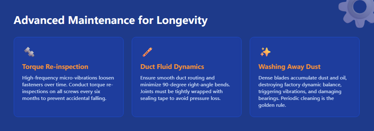
- Regular Torque Re-inspection: No matter how secure the initial installation is, the high-frequency micro-vibrations of the fan over months and years may loosen fasteners. Conducting a torque re-inspection on all installation screws and brackets every six months is a safety guarantee to prevent the fan from accidentally falling.
- Fluid Dynamics of Duct Connection: If your fan system is connected to external flexible ventilation hoses or galvanized ducts, be sure to ensure smooth duct routing and minimize 90-degree right-angle bends. Joints must be tightly wrapped with sealing tape to avoid pressure loss and airflow howling caused by air leakage.
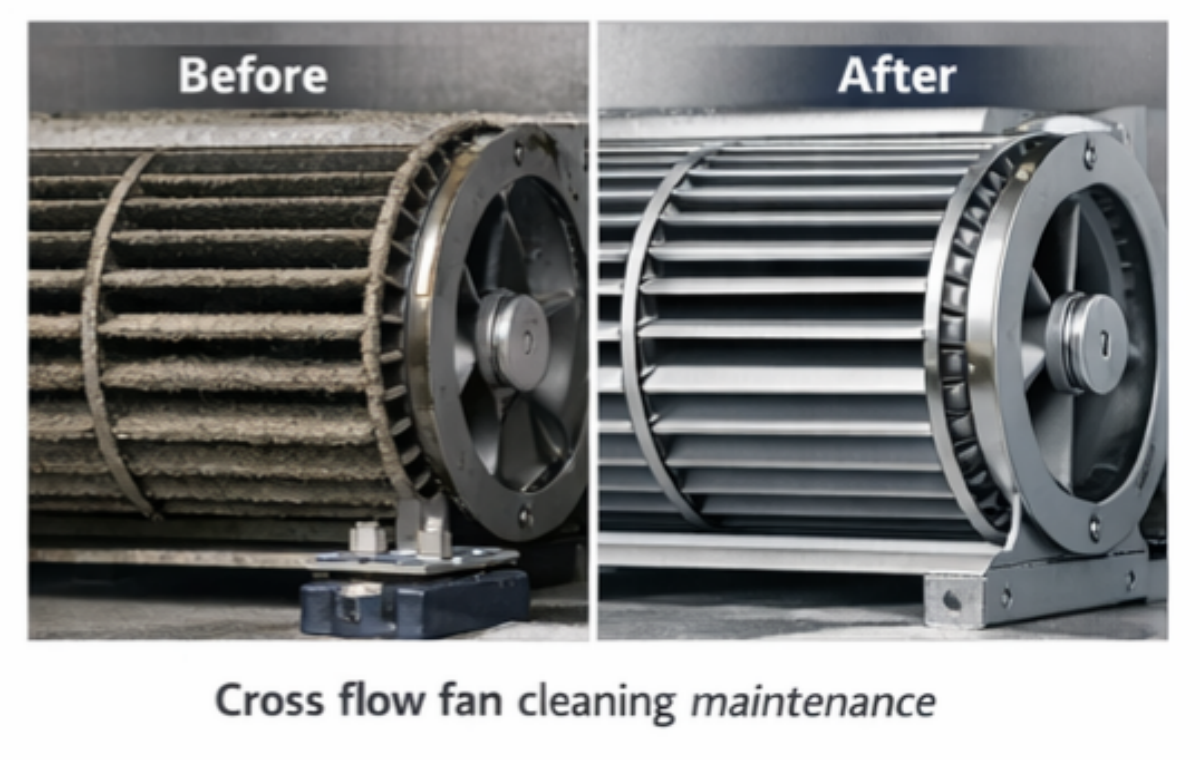
- Washing Away the Dust (Maintaining Impeller Dynamic Balance): The dense blades of a cross-flow fan are most susceptible to accumulating dust, lint, or industrial oil stains. Failure to clean it for a long time will lead to an uneven increase in the local weight of the impeller, completely destroying the dynamic balance state from the factory, triggering severe vibrations, and damaging the motor bearings. Therefore, formulating a strict periodic cleaning plan is the golden rule for maintaining the fan’s peak performance.
For more information, please contact LONGWELL.
Official website: www.longwellfans.com
Contact email: sales@zjlongwell.com