An AC condenser fan motor replacement is an identity-and-verification job, not a visual match. A motor that fits the opening can still have the wrong electrical architecture, control interface, rotation convention, shaft geometry, overload arrangement, or approved operating envelope. The safest decision is to bind the replacement to the exact outdoor-unit record, the complete old-motor identity, and the current manufacturer procedure before any part is installed.
This guide is written for qualified HVAC service personnel. It does not replace the equipment service literature, the motor maker’s instructions, site energy-control rules, or applicable electrical requirements. The video below is a visual overview of the same decision path; it is not evidence that one motor is interchangeable with another.
Define the replacement boundary before selecting a motor
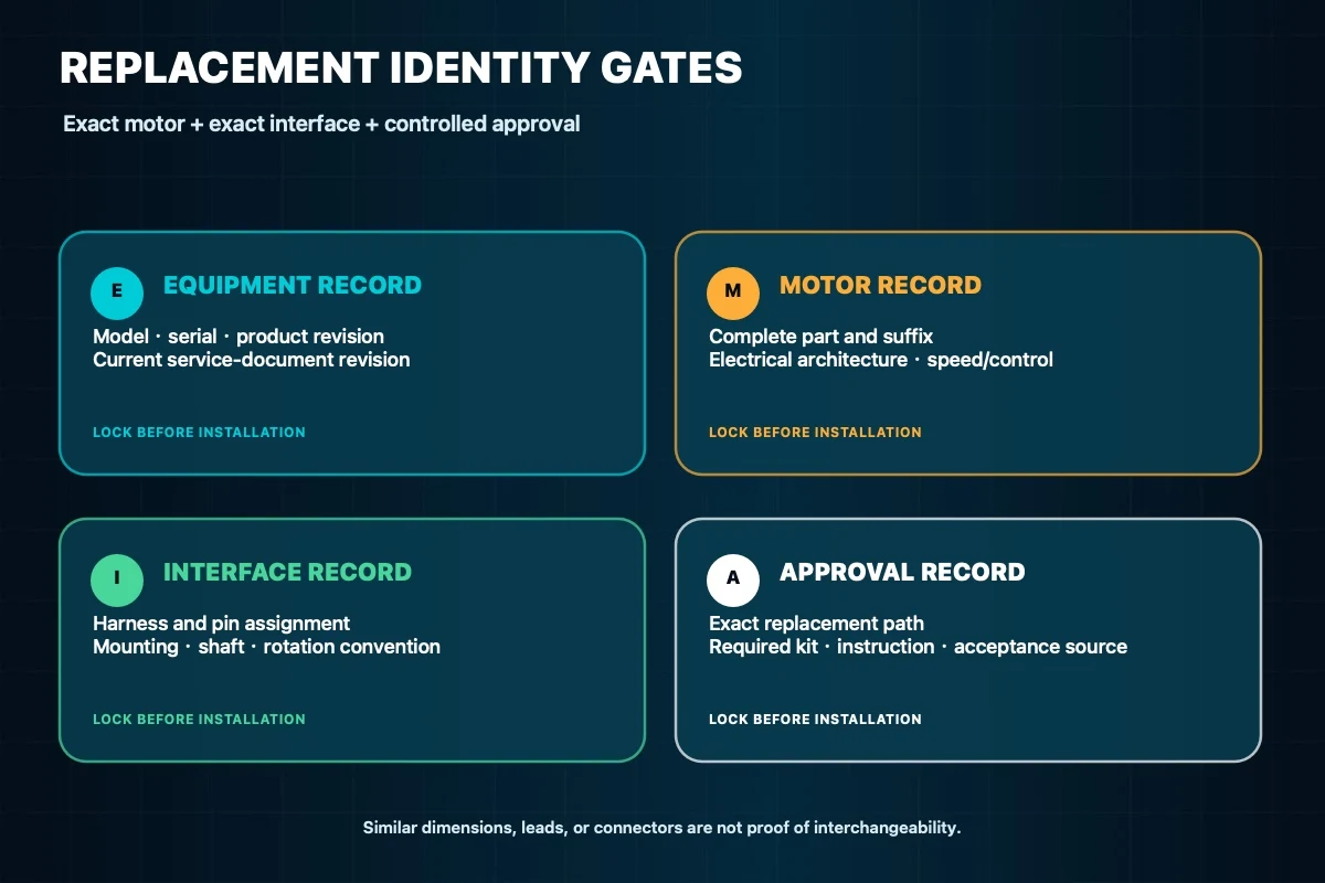
Start with the outdoor unit’s model, serial number, product revision, and the service-document revision used for the job. Then record the complete installed motor nameplate and part number, including every suffix. Photograph the connector, mounting, shaft, fan blade, lead exit, and any controller or capacitor called out by the equipment documentation. Keep these records together so the electrical and mechanical interfaces cannot be approved independently by mistake.
A fan curve guide explains why airflow acceptance belongs at the installed duty point rather than at a free-air maximum, but a generic curve cannot approve a field replacement. Compatibility must come from controlled equipment and motor information.
Lock the exact motor and interface identity
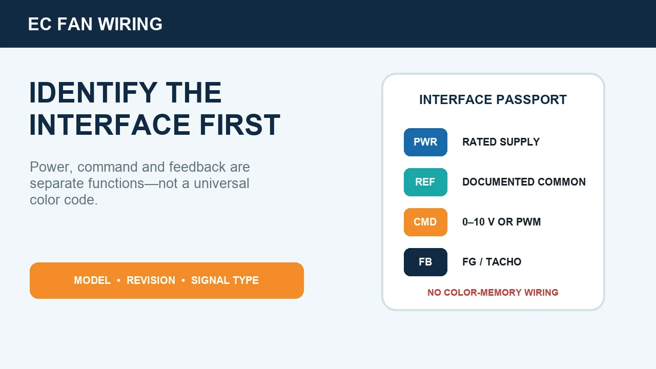
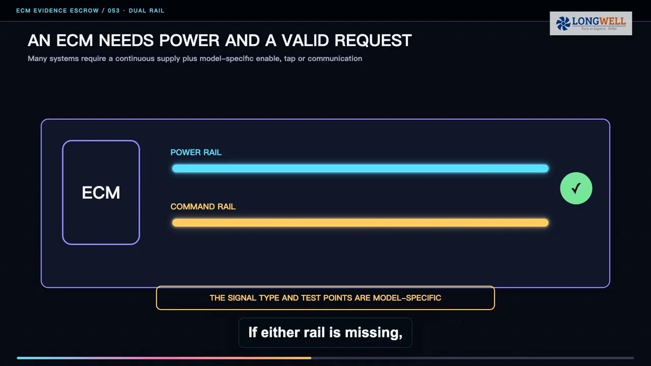
Compare the proposed replacement against the approved service path, not against appearance or wire color. The review should cover motor technology, rated supply, frequency and phase, permitted speed or speed taps, rotation with its stated viewing convention, thermal protection, duty, enclosure, and any equipment-specified capacitor. For an electronically controlled motor, also lock the controller, harness, pin assignment, command method, feedback, addressing, and required configuration. A familiar plug shape is not a pinout.
Resolve every discrepancy before installation. A supplier cross-reference is useful only when it identifies the exact unit boundary, replacement part, suffix, revision, and any required kit or instruction. Do not generalize a bulletin, drawing, or nameplate from another product family.
Verify the installed electrical boundary
With hazardous energy controlled, inspect the branch connection, grounding or bonding path, terminals, conductor condition, protective devices, and motor circuit against the unit procedure. If the approved design uses a separate capacitor, match only the value, voltage class, connection, and replacement method specified for that exact motor and unit. Do not infer a capacitor or wiring scheme from a generic diagram.
Plan the operational checks before restoring energy. Record the supply condition and installed motor current under a defined operating state, then compare them with the applicable equipment and motor limits. The measurement method, access arrangement, instruments, and acceptance limits must come from the authorized procedure. A bench spin or unloaded observation does not establish installed load.
Match shaft, mounting, blade, and clearances
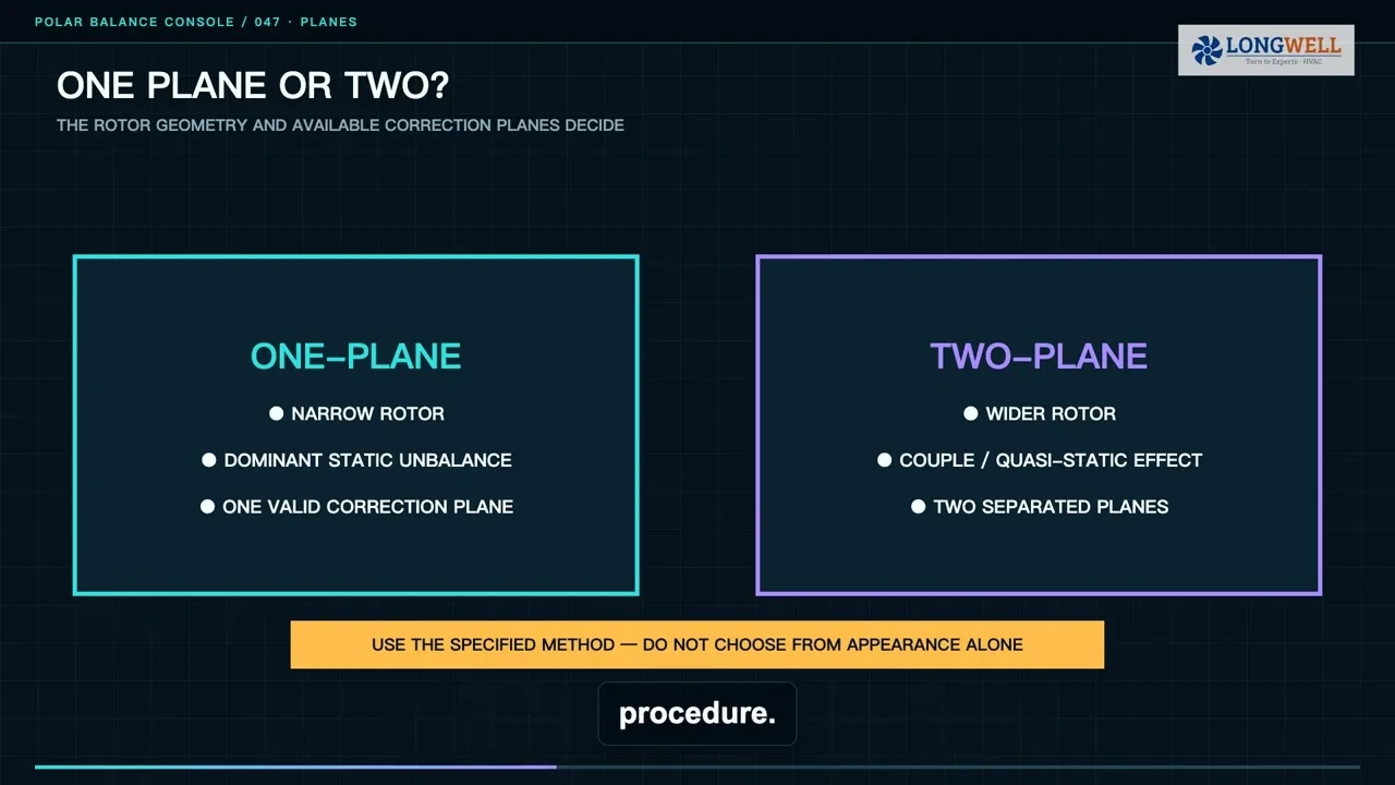
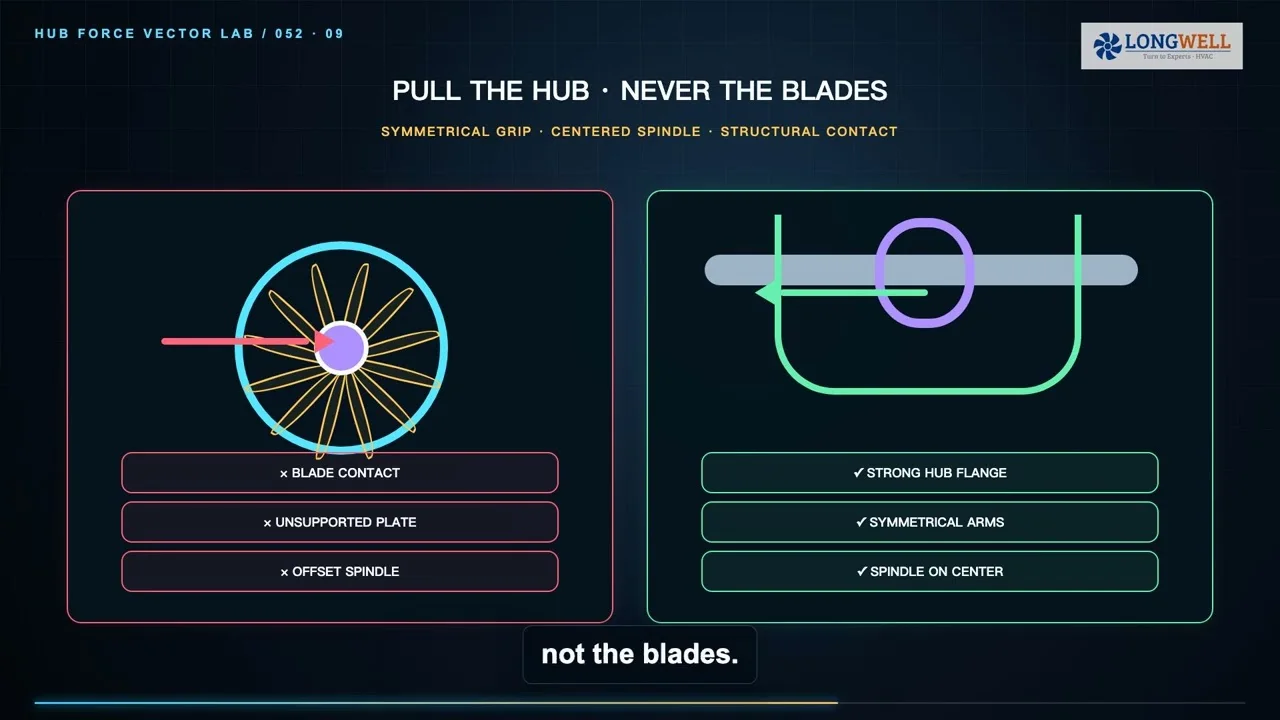
Mechanical interchangeability includes the mounting pattern and hardware, motor frame and orientation, shaft diameter and usable length, flats or keys, lead exit, weather protection, and service clearance. For the fan blade, verify hub and bore, attachment method, diameter, pitch and orientation, rotation convention, axial position, tip clearance, and clearance to the guard, coil, wiring, and cabinet.
Record the approved blade datum before removal. Do not blindly copy a blade height from a damaged, shifted, or previously serviced assembly. Inspect the blade, hub, fastener, guard, and supports for cracking, distortion, corrosion, looseness, or evidence of contact. A suspect blade or hub needs its own approved disposition rather than being transferred automatically.
Remove and assemble without changing the evidence
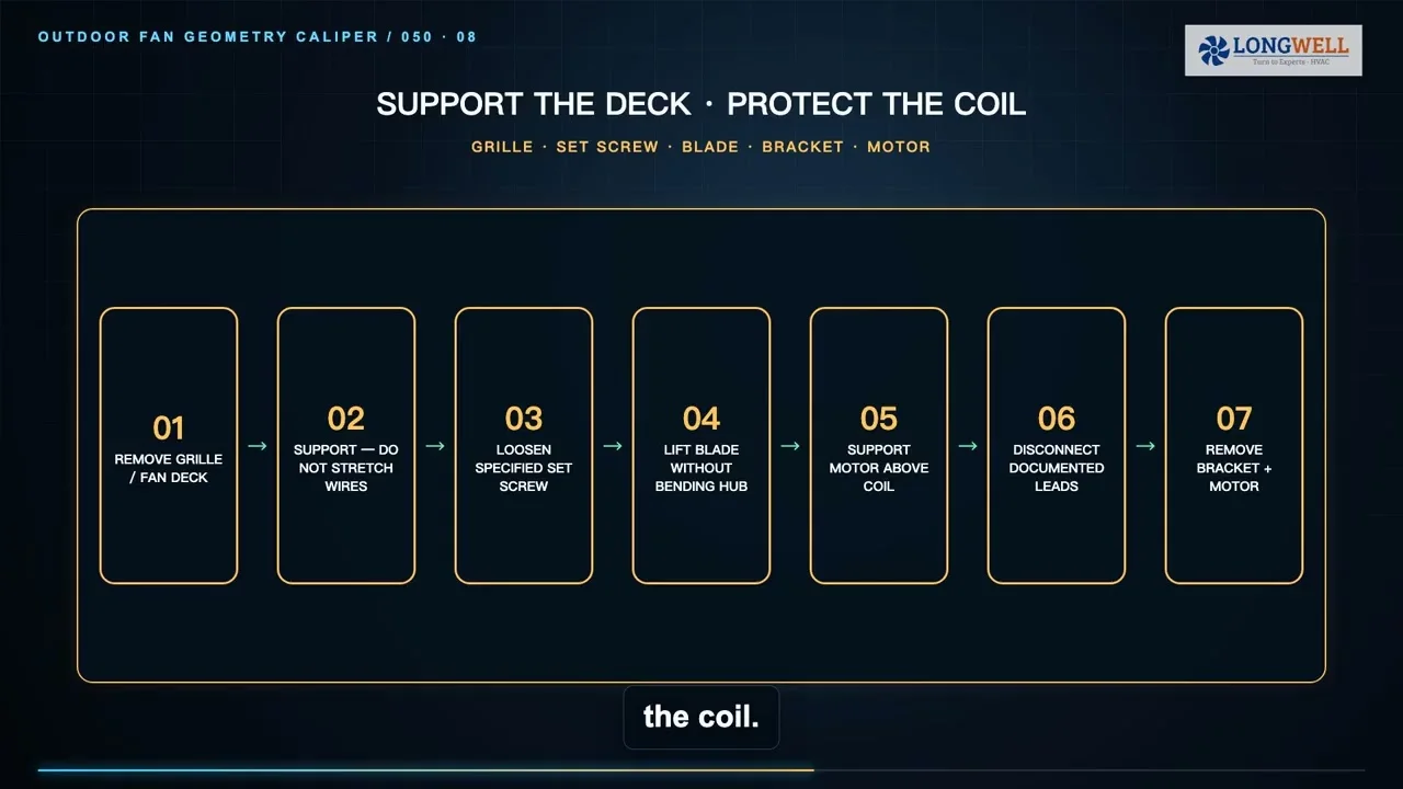
Apply the site’s hazardous-energy procedure, verify the de-energized state using the authorized method, and follow the equipment procedure for stored electrical energy. Mark and document connections by terminal or connector identity, never by a universal color assumption. Support the blade and motor during removal, use the specified extraction method, and avoid impact that could damage the hub, shaft, bearings, coil, or cabinet.
During assembly, use the specified fasteners, locking features, routing, strain relief, sealing, and tightening method. Confirm free rotation by the approved manual check, verify clearances through the full path, and restore every guard, panel, weather seal, and protective feature required for the planned test state.
Use a controlled restart, not an open-panel shortcut
Temporary test energy requires a controlled sequence: clear personnel and tools, restore the test-ready configuration, authorize energization, observe from the protected position, then de-energize and reapply energy control before any further contact. Control circuitry alone is not an energy-isolating device. If live measurement is required, it belongs to qualified personnel using the unit-specific method and a guarded access arrangement.
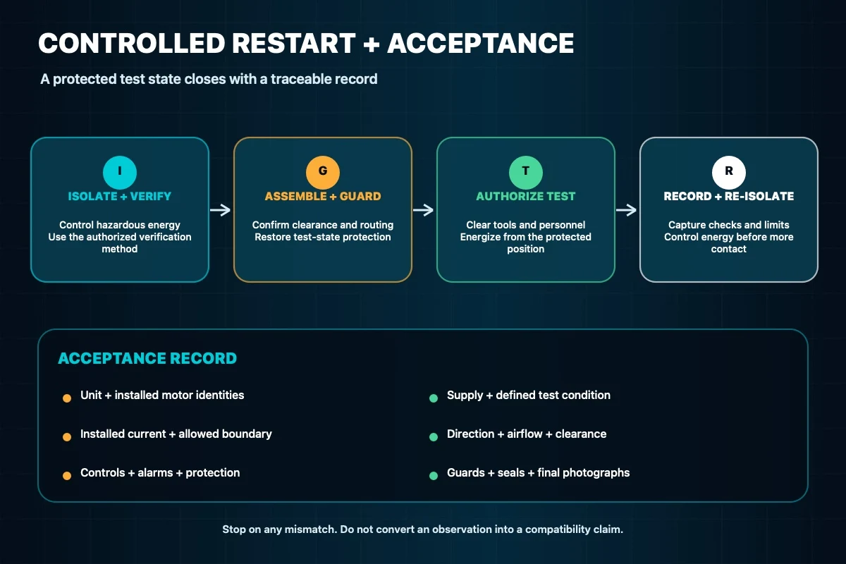
At startup, confirm the documented direction convention, fan airflow direction, stable clearance, and absence of rubbing or abnormal movement. Observe the equipment controls and protective response required by the service procedure. Stop on a mismatch, contact, unstable behavior, unexpected alarm, or measurement outside the approved boundary; do not keep running in an attempt to prove that the part will settle in.
Close the job with an acceptance record
The handover record should bind the unit model and serial, removed and installed motor identities, replacement authorization, service-document revision, blade and mounting observations, electrical configuration, test condition, supply and installed current, direction and airflow checks, clearances, alarms or protective events, restored guards and seals, final photographs, technician, and date. Record the actual acceptance source and result without promising a universal service life, energy saving, temperature change, or customer outcome.
For equipment development or a controlled redesign, the LONGWELL condenser cooling fan family is a family-level starting point only. An RFQ should still include the exact airflow and pressure boundary, mechanical envelope, supply and control interface, environmental limits, drawing revision, test method, and acceptance record required for the application.